1. The board
| Board | Arduino Mega 2560 + RAMPS 1.4 shield |
| Firmware | GRBL Mega-5X — HotWire4X variant, version 1.2i, build 20260701 or later |
| Axes | 4 — XYZA |
| Link | USB, virtual serial port, 115200 baud |
| Power | USB for flashing, 12 V - 5 A power terminal block for operation |
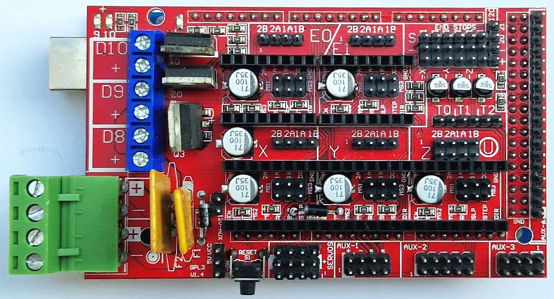
This board is getting old, but it works, it is cheap, and there are quite a few of them around, so I decided to support it in HotWire4X, with a dedicated firmware.
2. Why a recompiled firmware
Existing firmware always lacked something to be a perfect fit for hot wire cutting. That is why I compiled this version, which provides:
- A heating PWM output that does not go to one of the board’s MOSFETs, that is easy to reach (and close to a
GNDpin), because you need to be able to use an external heating controller to power the wire of a real hot wire CNC at the voltage it needs (usually 48 V in hobby practice) — not just the RAMPS’s 12 V maximum. - A STOP button that stops the movement AND cuts the heating, wired to the board’s “door” input (originally meant for the guard door of a machine tool): the movement slows down to a stop, the heating cuts out, the motors stay energized and the wire position stays exact. It has the same effect as the STOP button of the Cutting tab.
- Push buttons in “normally open”, because we are talking about hobby practice and low-power machines, and this gives you an interface that does not go into an error state at power-up. (On this board, unlike the SKR Pico, this choice is fixed in the firmware: it cannot be changed from HotWire4X.)
⚠ The STOP button is not an emergency stop: it does not cut off any power supply. Your machine must have a true emergency stop, which cuts off the power to the motors and to the heating.
3. The heating architecture: the point not to miss
To heat the wire, you can find plans on the Internet for hot wire cutting machines that use the MOSFET intended for a 3D printer’s heated bed (= you connect the cutting wire to the RAMPS’s D8 terminal block, and you have a single power supply for motors + board + wire heating).
It is tempting because it is simple, but the problem with this setup is that this power stage is designed for a supply voltage of 12 V maximum. (There is a hack to go to 24 V, but let’s not go there, OK? 😅)
At 12 V, the power available for the wire is low: it only allows very short wires and/or very slow speeds. In other words, a really small machine — and for a really small machine, the RAMPS is too bulky: a BTT SKR Pico does the same job in a much more compact format, and accepts 24 V directly.
That is why I do not offer an “on-board heating” firmware for the RAMPS.
The only firmware I offer is therefore for hot wire cutting machines of a size suited to versatile 4-axis cutting:
- it brings the heating control PWM signal out on an easily accessible pin (pin
D6of theSERVOSpin group, with aGNDpin close by), - to drive a separate power stage, supplied at 48 V,
and thus get enough heat for a machine that uses 4-axis cutting on a table up to 1 m wide, to cut all polystyrenes and EPP.
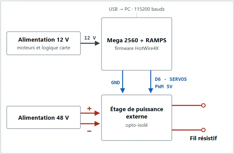
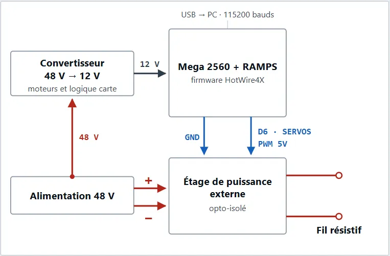
Such a setup also allows the heating to be opto-isolated from the microcontroller. It requires 2 supply voltages: 12 V for the RAMPS and the motors, 48 V for the wire heating.
There are two options for the power supplies, exactly as for the SKR Pico:
- Either two separate power supplies (12 V for the RAMPS and the motors, 48 V for the heating):
- Or one 48 V power supply for the heating, and a 48 V → 12 V converter for the RAMPS and the motors:
4. The firmware
| Firmware name: “RAMPS 1.4 - HotWire4X PWM-D6 - R.ILTIS” |
|---|
| It is intended for 4-axis hot wire cutting machines with a separate heating power supply and controller. |
It exposes the 5 V PWM signal (meant to drive the heating) on pin D6 of the SERVOS pin group of the RAMPS. It also provides points 2 and 3 above. The heated bed’s D8 power output is no longer used for the heating. |
| → This is the RAMPS firmware on the Downloads page! |
5. Powering the motors + board: 12 V, and no more
You can power the board’s logic from the USB cable to flash the firmware and check that the software recognizes it — the Arduino Mega 2560 powers itself over USB, with no jumper to install.
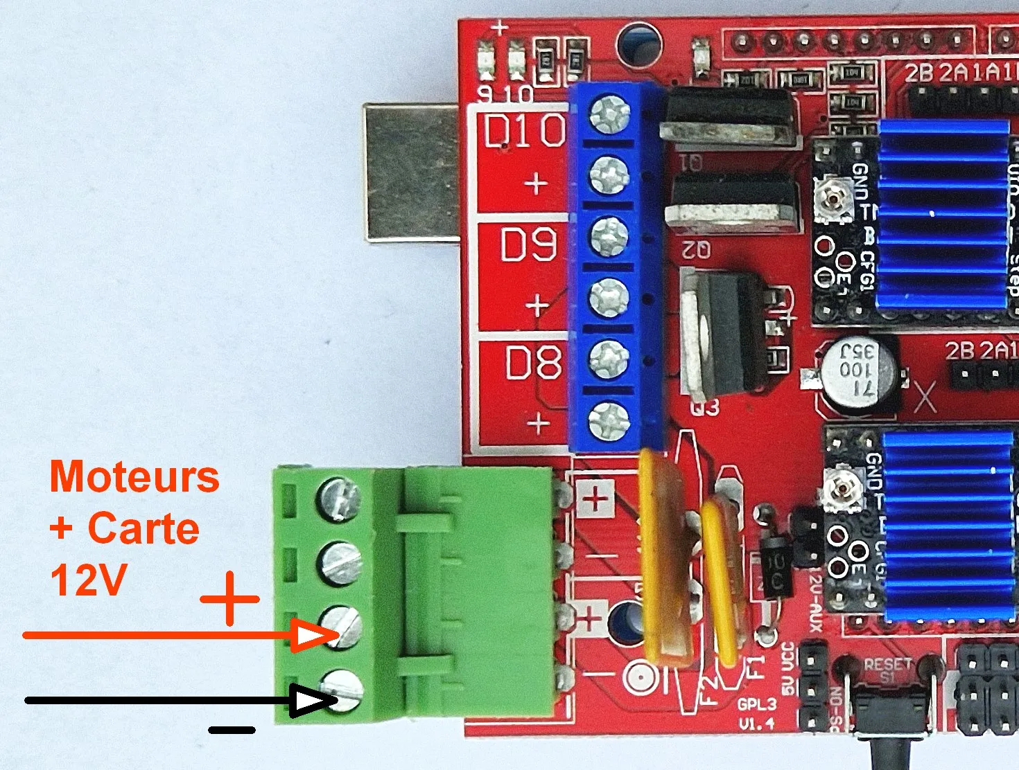
To run the machine, the motors must be powered through the RAMPS’s power terminal block, at 12 V — in that case, the Arduino Mega 2560 powers itself from the 12 V through a regulator built into the board.
6. Drivers, microsteps and motor current
Unlike the SKR Pico, the RAMPS has no built-in drivers: you use small plug-in modules (A4988, DRV8825, TMC2208/2209 for example).
Get all four of the same model so the four axes behave the same way.
On the RAMPS, the microsteps are set with the three jumpers MS1, MS2, MS3 located under each driver, between the two rows of pins.
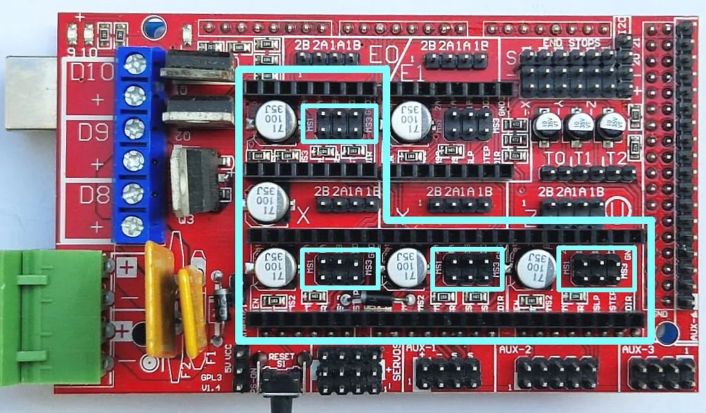
The combination of jumpers to install depends on the number of microsteps you chose and on the driver model: refer to the driver’s settings table — it should come with the driver when you buy it, since it depends on the driver type.
Write down the microsteps you set: you will need to enter them in HotWire4X.
Then you can plug in the drivers and set the motor current with the small potentiometer on each driver.
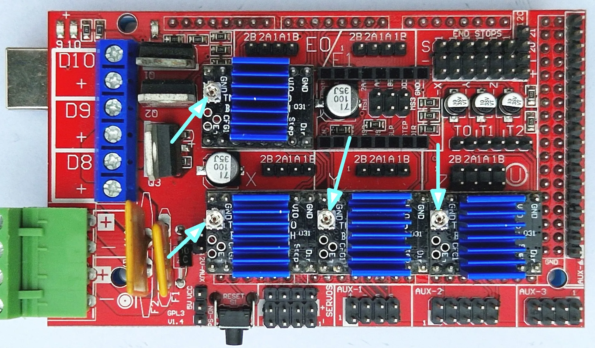
Here, there are as many methods and formulas as there are driver types, so I refer you to the documentation that came with your purchase (and if it is not clear, complain to the seller and ask for details!).
CAUTION:
- Never plug in or remove a driver while powered, and never unplug a motor while powered — high risk of frying the driver!
- Always check the driver’s orientation before plugging it in: the driver’s
ENpin goes to the RAMPS’sENpin. Backwards, it burns out at power-up.
7. Flashing the firmware the easy way (= transferring the new firmware into the board)
On the Arduino Mega, the firmware is a .hex file that has to be sent to the board over the USB cable.
And for that you are simply going to use HotWire4X!
-
Download and install HotWire4X if you have not already done so.
-
Download the Mega 2560 + RAMPS firmware. It is the file
grbl-Mega5X-HotWire4X.hex. -
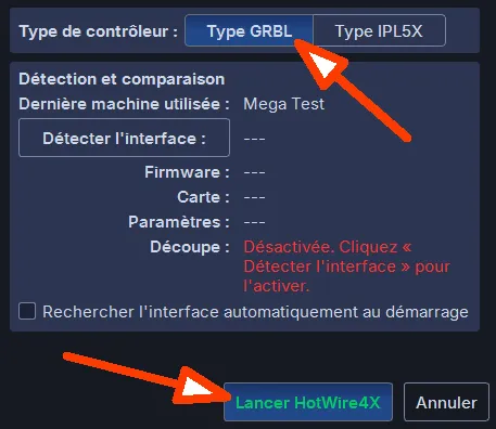
Start HotWire4X, then click GRBL type, then Launch HotWire4X.
-
Connect the Mega 2560 + RAMPS board to the computer with a USB cable.
-
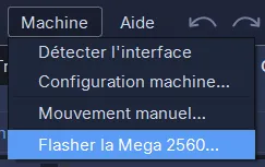
Open the menu
Machine > Flash the Mega 2560...
- Using it is intuitive:
- click Browse… to find the
.hexfile you downloaded, - make sure “Verify after writing” is checked,
- if needed, click Refresh to update the COM port the board is connected to,
- click Flash.
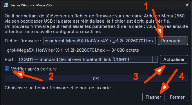
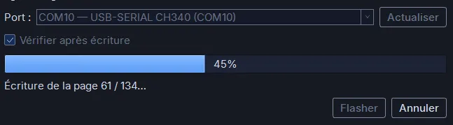
The transfer takes place in a few seconds, the board’s LED blinks, then the board restarts by itself.
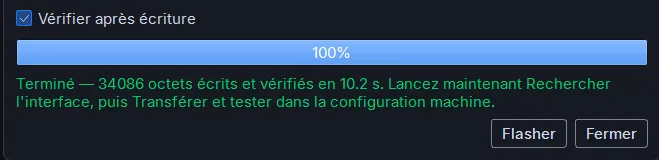
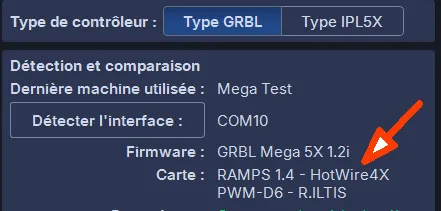
- Test that HotWire4X recognizes the board: go back to the start screen with the ⬆️ button at the top right, select GRBL type on the start screen and click Find interface.
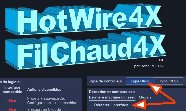
- If everything went well, you should see the firmware name displayed:
RAMPS 1.4 - HotWire4X PWM-D6 - R.ILTIS.
→ The current firmware versions are on the Downloads page.
8. Complete wiring
On the RAMPS, the PWM output and the STOP button connect to two easy-to-spot areas:
| Function | Area on the RAMPS | Pin |
|---|---|---|
| Heating PWM output (to the 48 V module) | SERVOS connector | D6 (5 V signal, 244 Hz) and GND |
| STOP button | AUX-2 connector | A12 and GND |
| Pause (optional) | AUX-2 connector | A10 and GND |
| Resume (optional) | AUX-2 connector | A11 and GND |
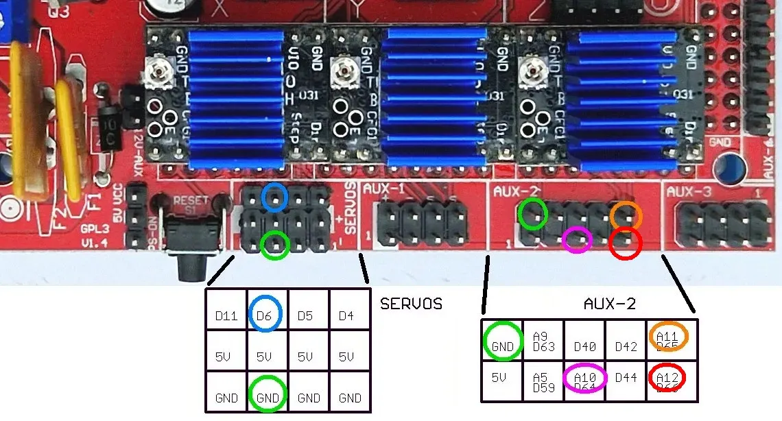
The STOP button is wired between A12 and the GND ground of the AUX-2 connector: it is a “normally open” push button, and a press pulls the pin to ground. These two pins are at opposite corners of the connector.
Do not connect anything to A9: it is the Reset input; it restarts the board and the wire position is lost.
Physical Pause and Resume buttons are of no real use: HotWire4X has them on screen, Pause and Resume. If you want them anyway, they are wired the same way to A10 and A11, and share the single GND ground of AUX-2 with the STOP button.
Here is the complete wiring with the USB cable, the motors and the motor + board power supply:
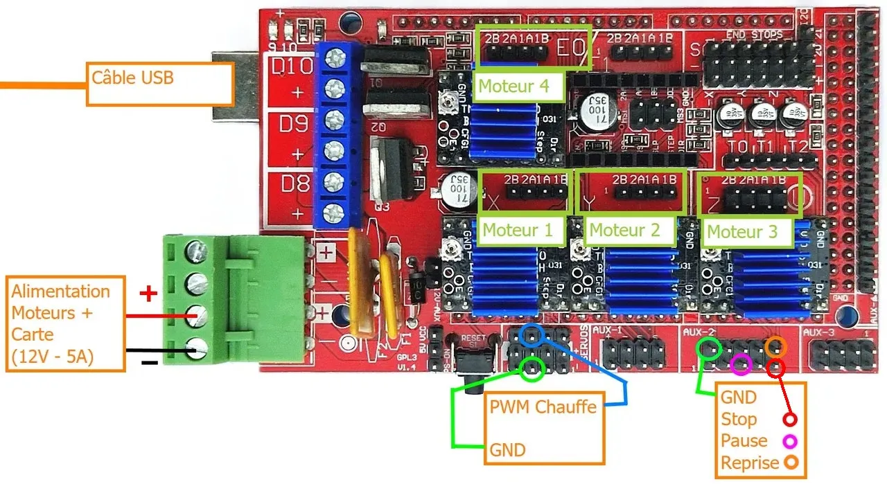 Limit switches are not shown: they are not needed in hot wire CNC cutting when the machine is designed properly.
9. Setting up the interface in HotWire4X
HotWire4X includes templates for the interfaces presented on this site.
This makes setup quick: you start from the template, then go through the values to adapt them to your actual machine.
Using a template:
- Go to the menu
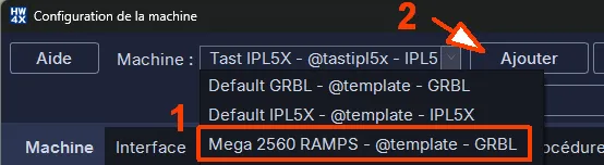
Machine > Machine configuration...to open the Machine Configuration window. - Click the drop-down list, choose the “Mega 2560 RAMPS - @template - GRBL” template then click Add to create a new machine based on this template.
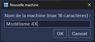
- Enter your machine’s name. Use a meaningful name that lets you recognize it (not the name of its interface); you have 16 characters for that. Then OK.
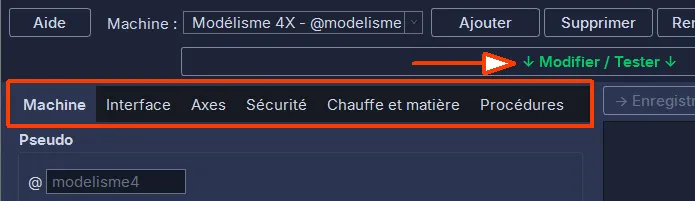
- You can already click the Machine, Interface, Axes, Safety, Heating and material, Workflow tabs to see what they contain. But to be able to change the values, you first have to click the ↓ Modify / Test ↓ button.
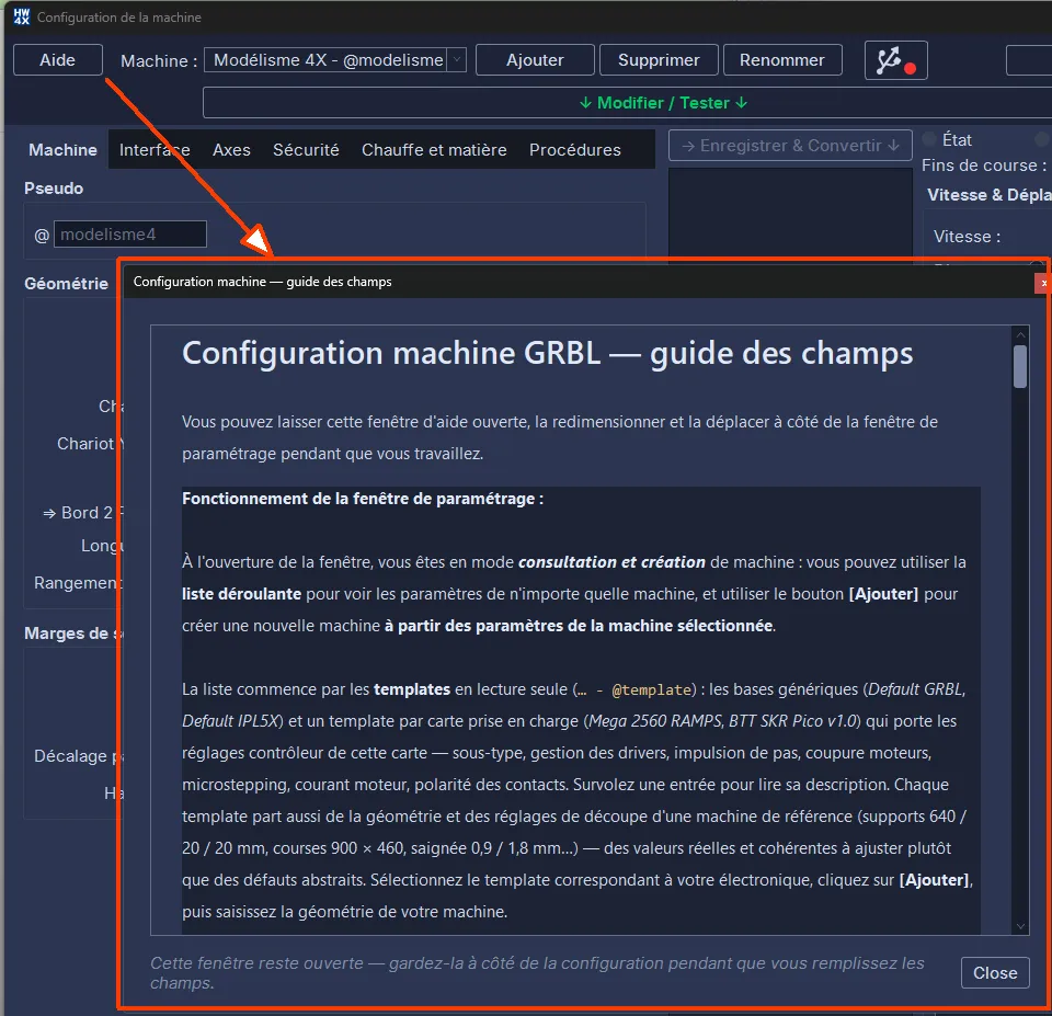
- Now you can change all the settings in all the tabs. And you can bring up a window explaining every field by clicking the Help button:
If you have trouble understanding the settings, take a look at the coaching I offer and/or refer to the software’s user manual.
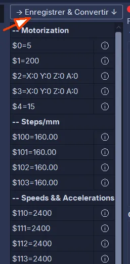
- Once the settings are entered, click → Save & Convert ↓ to generate the interface’s configuration instructions:
-
Check all the ”$” settings in the list. If one does not look right, change the corresponding content in the tabs, then click → Save & Convert ↓ again.
-
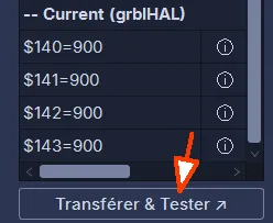
Once the settings are right, it is time to transfer them into the interface (which must be connected). To do so, click Transfer & Test ↗ at the bottom of the list.
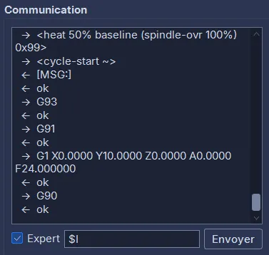
- At the bottom of the column you can watch the exchange of information between the software and the interface, and you can send your own G-code instructions by checking the ☑️ Expert box + Instruction + Send (for example, you can send
$Ito check that you have the right firmware: the board must answer[BOARD:RAMPS 1.4 - HotWire4X PWM-D6 - R.ILTIS]).
10. Tests and adjustments
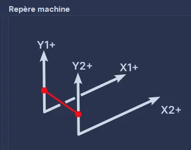
This is the moment of truth: power up your machine — you are going to use the test panel (the right-hand column of the window) to test the axis movements so that they match the diagram below. Then you will test the heating.
10.1 Preliminary checks
- Green status light in the button with the USB symbol (1, see below).
- In the test panel, the status light must show Idle (2).
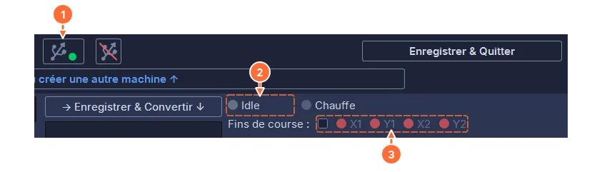
- If the limit switches are enabled (box checked), their lights must be grey for movements to be possible.
10.2 Adjusting axis pairing and direction
You are going to test the movements axis by axis and, if needed, correct the order of the letters and the direction of travel in the Axes tab to match the diagram in §10 above.
-
Move the carriages on all axes by hand to put them roughly mid-travel (to avoid jamming against the end stops).
-
Speed: 4 mm/s. Distance: 10 mm. Select the X1+ direction under Side 1 and press GO.
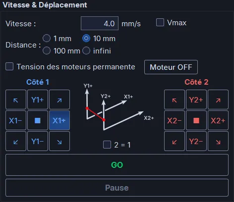
The movement must happen on the right axis and in the right direction (see the diagram in §10). If it does not, change the settings (axis letter and direction) until it is right.
⚠ After every change, click → Save & Convert ↓ then Transfer & Test ↗ again to update the settings in the interface.
- When an axis is right, move on to the next one.
10.3 Adjusting the resolution
-
Tape a steel rule, tape measure, etc. along the X1 axis and bring the wire to 0 (or simply make a pencil mark to set the start of the movement).
-
Make a 100 mm move in X1+ in the software and measure the actual distance.
-
If you have a big gap (say you ask for 100 mm and it moves 50 mm), the “Microsteps” field probably does not match the
MS1-MS3jumpers of your drivers (see §6). Correct it. -
If you have a small gap, adjust the “mm / revolution” field with a simple proportion, testing until you get exactly the requested movement.
-
Repeat for Y1, X2, Y2.
10.4 Adjusting the wire’s maximum electrical power
-
Check that the wire is completely clear, touches nothing, and that the electrical insulation is perfect from the rest of the machine.
-
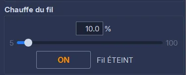
Set the power to 10% and start the heating by clicking ON.
ℹ️ You may see the heating go very briefly through 50% before dropping back to 10%. This is normal: it comes from the procedure that lets you adjust the heating during a movement.
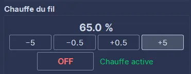
- Increase the heating in 5% steps using the +5 button.
-
The goal here is to find the maximum electrical power the wire can take without melting it. Watch its colour: when it turns “cherry red”, do not go any further, or it may melt and break.
-
Enter this value in the “Maximum Electrical Power” field of the Heating and material tab and repeat the → Save & Convert ↓ then Transfer & Test ↗ procedure. This changes the heating scale directly in the interface: even if the display shows 100% heating, the electrical power will be spread over the new scale and you will not melt your wire.
10.5 Testing the STOP button
-
Switch the heating on (§10.4), start a long move (§10.2, for example 100 mm) and press the STOP button: the movement slows down to a stop and the heating cuts out. HotWire4X hands control back to you at once, with no window, and the board accepts the next command.
-
If you wired Pause and Resume, make another move and test Pause then Resume: the movement stops, then picks up where it left off.
11. Validate and cut
When everything is OK, make sure to save your settings. To do so, click:
- ↑ Save and select or create another machine ↑
- or/then Save & Exit

You are now ready to cut. For example, you can go back to the start screen with the ⬆️ button at the top right, launch again, and click Load the example on the welcome sticky note.
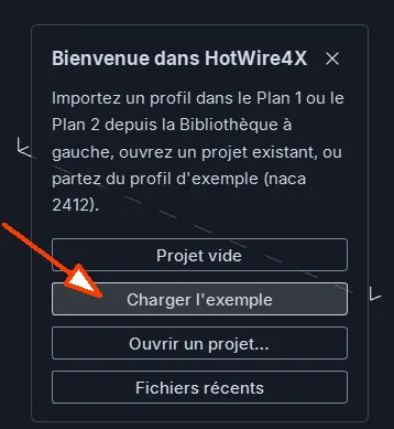
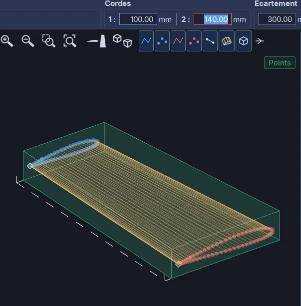
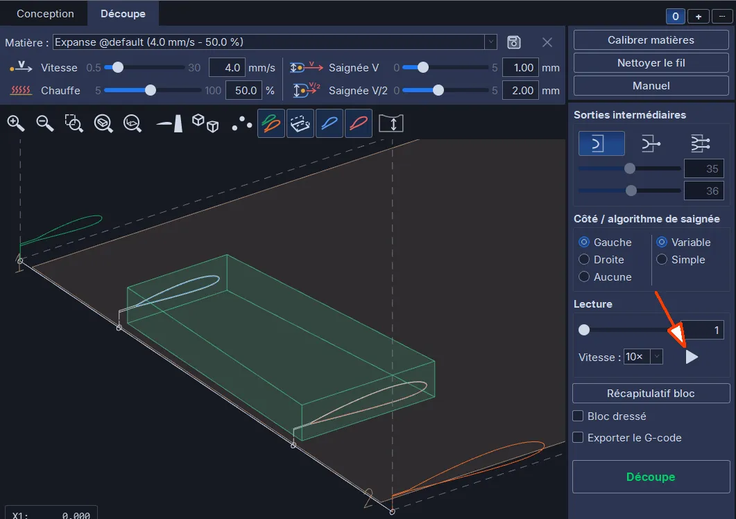
Then change the value of a chord and go to the Cutting tab to see the result. And click the button in the Simulation frame to watch the cutting simulation:
To run a real cut you need a licence: see here which one suits you.
Enjoy your machine and HotWire4X, launch some crazy cuts, and share your projects on cncpartage.fr!