1. Meet the IPL5X
The IPL5X is not a control board: it is a 5-axis interpolator, designed by Pascal Langer as part of the 5X-Project (see the Story section).
It is a USB HID device, like a computer mouse, which means it is recognized automatically. For a 4-axis hot wire table, only 4 of the 5 possible axes are used.
It receives movement vectors and the heating percentage into a buffer, in USB bursts (no G-code), from which it computes and generates the dir/step pulses of the 4 axes and the heating PWM simultaneously. All of it based on its internal clock (quartz crystal), for precise, synchronized movements.
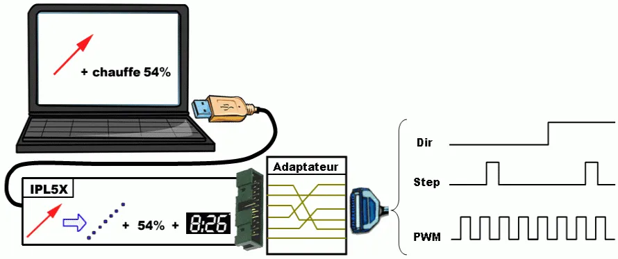
Originally it was a board that sat between the computer and a board driven directly in dir/step through a parallel port, plus a heating controller.
When I was building hot wire CNC cutting machine kits, from 2013 to 2025, I designed boards that combined the IPL5X, the drivers, and the heating control at 12 V or 48 V (depending on the machine’s size).
For now these boards are no longer produced and no longer for sale. They do, however, equip the hundreds of machines I produced and a number of hobbyist machines.
HotWire4X therefore supports the IPL5X protocol just like my previous software did, but you absolutely must check the firmware version (see below).
| Board | Any IPL5X variant |
| Firmware | version 0.34 exclusively (see below) |
| Link | USB, HID device (no “COM” serial port) |
| Power | the logic of the board and the drivers can be powered from USB alone if the board is well designed — but it depends on each board |
2. Firmware 0.34 is mandatory
Version 0.34 is the only supported version, and the only one I make available.
Version 0.33 — still distributed by the 5X-Project archive — will not be blocked, but is not considered a compliant use of the HotWire4X software.
The difference is that if you press the STOP button (the push button connected to STOP ) while the carriages are stopped AND the wire is heating:
- the heating is not cut on 0.33 (more precisely, it is cut and then turns back on),
- while it is truly cut on 0.34.
So 0.34 brings an extra layer of safety.
If the wire is moving when the button connected to STOP is pressed, both versions behave the same: the heating is cut at the same time as the movement.
3. Checking the installed version
Checking your firmware version is simple:
-
Download and install HotWire4X if you have not already done so.
-
Connect your IPL5X interface to the computer.
-
Start HotWire4X and, on the start screen, click IPL5X type then Find interface: HotWire4X will give you the firmware version.
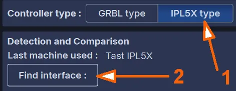
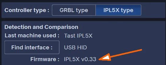
- If you are not on version 0.34, the board has to be reflashed. To do so, launch the software by clicking Launch HotWire4X and go to §4.
4. Flashing the firmware
-
Download the IPL5X v0.34 firmware. It is the file
IPL5X_v0.34-HotWire4X.hex. -
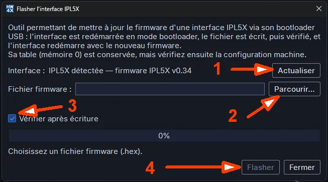
Open the menu
Machine > Flash the IPL5X...
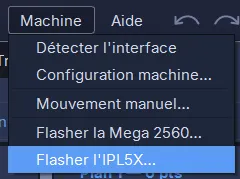
- Using it is intuitive:
- if needed, click Refresh if the board was not plugged in,
- click Browse… to find the
.hexfile you downloaded, - make sure “Verify after writing” is checked,
- click Flash.
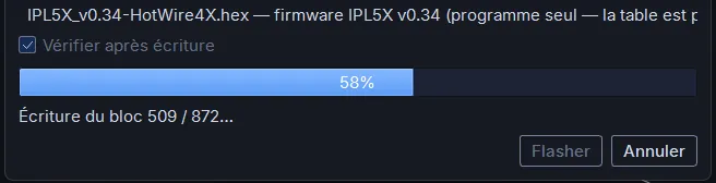
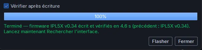
The transfer takes place in a few seconds, then the board restarts by itself.
-
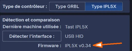
Test that HotWire4X recognizes the board: go back to the start screen with the ⬆️ button at the top right, select IPL5X type on the start screen and click Find interface.
-
If everything went well, you should see:
IPL5X - v0.34
→ The current firmware version is on the Downloads page.
5. Wiring
On the IPL5X, the STOP button must be a normally open (NO) push button and connects to the board’s STOP connector. It stops the movement AND cuts the heating.
⚠ The STOP button is not an emergency stop: it does not cut off any power supply. Your machine must have a true emergency stop, which cuts off the power to the motors and to the heating.
An LCD display and a 6-button keypad can be installed, but they are not useful in hot wire CNC cutting:
- I advise against installing the LCD.
- I advise against installing the keypad.
A manual heating control can be wired, using a potentiometer connected to POT_MANU and two toggle switches connected to ON/OFF and to PC/MANU. But here too, I recommend simplicity:
- No potentiometer.
- And the two switches are replaced with jumpers, so the heating is managed entirely by HotWire4X.
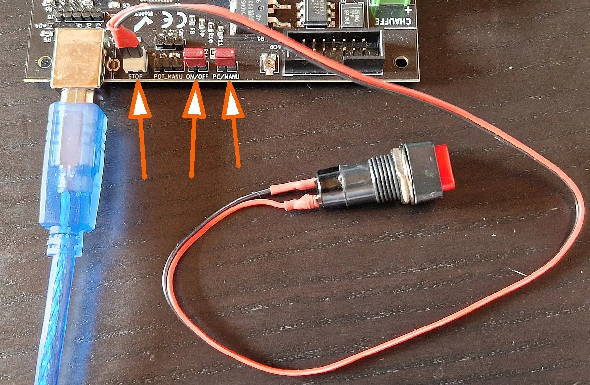
STOP is installed, and just two jumpers on ON/OFF and on PC/MANU.Note: There are no pins set aside for the Pause and Resume functions on the IPL5X, so you cannot have physical buttons for them, but these functions are available directly in HotWire4X, on buttons you can click during a movement.
The wiring of the power supplies and of the wire depends on the board each person has in hand. Refer to your hardware’s documentation.
6. Setting up the interface in HotWire4X
HotWire4X includes templates for the interfaces presented on this site.
This makes setup quick: you start from the template, then go through the values to adapt them to your actual machine.
Using a template:
- Go to the menu
Machine > Machine configuration...to open the Machine Configuration window. - Click the drop-down list, choose the “Default IPL5X - @template - IPL5X” template, then click Add to create a new machine based on this template.
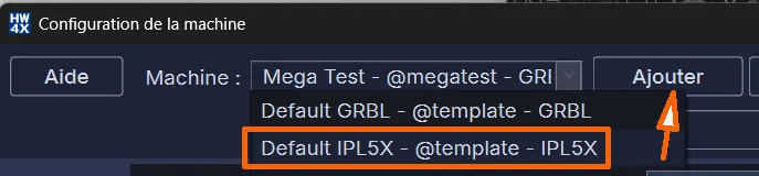
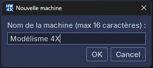
- Enter your machine’s name. Use a meaningful name that lets you recognize it (not the name of its interface); you have 16 characters for that. Then OK.
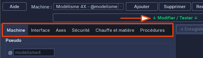
- You can already click the Machine, Interface, Axes, Safety, Heating and material, Workflow tabs to see what they contain. But to be able to change the values, you first have to click the ↓ Modify / Test ↓ button.
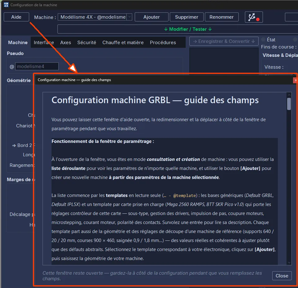
- Now you can change all the settings in all the tabs. And you can bring up a window explaining every field by clicking the Help button:
If you have trouble understanding the settings, take a look at the coaching I offer and/or refer to the software’s user manual.
- Once the settings are entered, click Save, Transfer & Test ↗ to save the settings and write them into the interface’s memory (which must be connected):
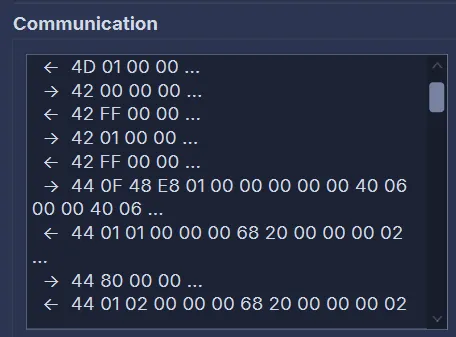
- At the bottom of the column you can watch the exchange of information between the software and the interface:
7. Tests and adjustments
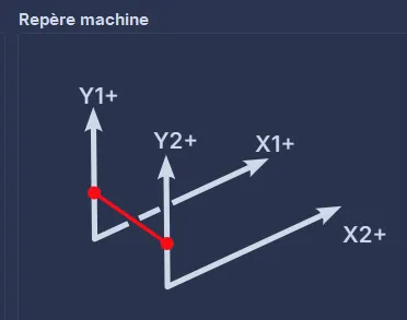
This is the moment of truth: power up your machine — you are going to use the test panel (the right-hand column of the window) to test the movements of the axes so that they match the diagram below. Then you will test the heating.
7.1 Preliminary checks
- Green status light in the button with the USB symbol.
- In the test panel, the status light is green and shows Ready.
- The limit-switch lights do not come on: when the feature is disabled — as it is by default — their state is not read by the IPL5X at all.
7.2 Adjusting the axis pairing and direction
You are going to test the movements one axis at a time and, if needed, correct the assignment of the STEP/DIR outputs and the direction of travel (“Invert” checkboxes) in the Axes tab, to match the diagram in §7 above.
-
Move the carriages on all axes by hand to put them roughly at mid-travel (so they do not jam against the end stops).
-
Speed: 4 mm/s. Distance: 10 mm. Select the X1+ direction on Side 1 and press GO.
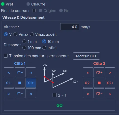
The movement must happen on the right axis and in the right direction (see the diagram in §7). If it does not, change the settings (outputs and axis direction) until it is right.
⚠ After every change, click Save, Transfer & Test ↗ again to update the settings in the interface.
- When an axis is right, move on to the next one.
7.3 Adjusting the resolution
-
Tape a steel rule, a tape measure, etc. along the X1 axis and bring the wire to 0 (or simply make a pencil mark to set the start of the movement).
-
Make a 100 mm move in X1+ in the software and measure the actual distance.
-
If there is a large gap (say you ask for 100 mm and it moves 50 mm), the “Microsteps” field probably does not match the actual setting of your board’s drivers. Correct it.
-
If there is a small gap, adjust the “mm / revolution” field by simple proportion, testing until you get exactly the requested movement.
-
Repeat on Y1, X2, Y2.
7.4 Adjusting the wire’s maximum electrical power
-
Check that the wire is completely clear, touches nothing, and that its electrical insulation is perfect from the rest of the machine.
-
Set the power to 10% and start the heating by clicking ON.
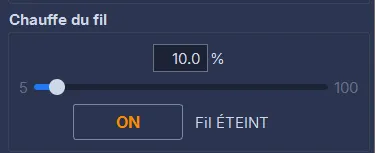
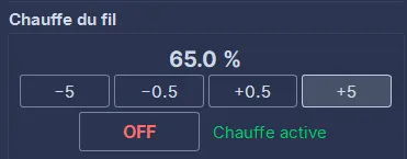
- Increase the heating in 5% steps using the +5 button.
-
The aim here is to find the maximum electrical power the wire can take without melting it. Watch its colour: when it turns “cherry red”, do not go any further, or it may melt and break.
-
Enter this value in the “Maximum Electrical Power” field of the Heating and material tab and click Save, Transfer & Test ↗ again. This recalibrates the heating scale: even if you set 100% heating, the electrical power will be spread over the new scale and you will not melt your wire.
7.5 Testing the STOP button
If you have wired the push button to STOP (see §5):
-
Start a long jog (§7.2, for example 100 mm) and press the button: the movement and the heating must stop immediately.
-
With the wire heating and the carriages stopped, press the button: the heating must cut out — this is precisely what firmware 0.34 brings (see §2).
Pause and Resume have no physical buttons on the IPL5X: test them with HotWire4X’s clickable buttons during a jog.
8. Validating and cutting
When everything is right, make sure to save your settings. To do so, click:
- ↑ Save and select or create another machine ↑
- or/then Save & Exit

You are now ready to cut. For example, you can go back to the start screen with the ⬆️ button at the top right, launch again, and click Load the example on the welcome sticky note.
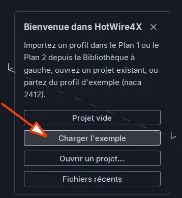
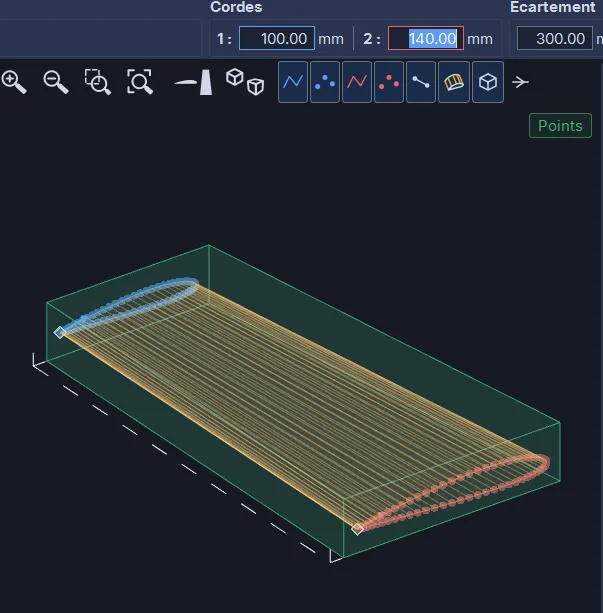
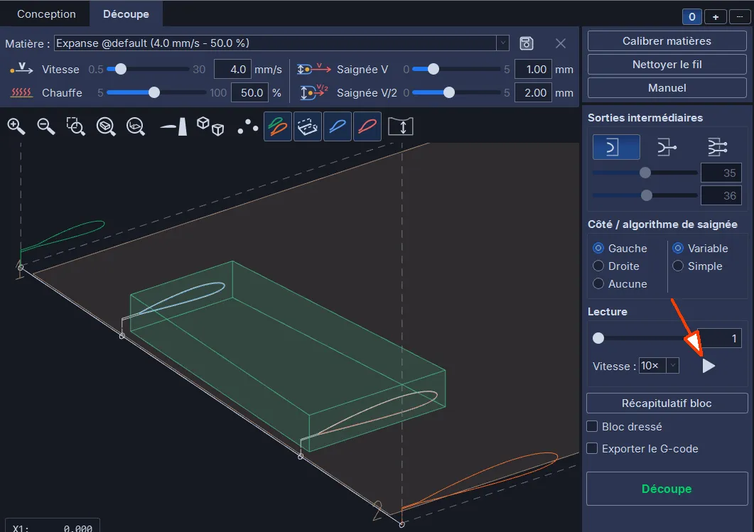
Then change the value of one chord and go to the Cutting tab to see what it gives. And click the button in the Simulation frame to watch the cut being simulated:
To run a real cut you need a licence: see here which one suits you.
Enjoy your machine and HotWire4X, launch some crazy cuts, and share your projects on cncpartage.fr!