The Assembly tab brings together all the elements of the workspace, the wings, the volumes built in segments and the volumes built from views, in a single 3D view where each one is placed, oriented and possibly duplicated. It is a check mock-up: you verify that the wing sits properly on the fuselage, that the proportions match the plan, that nothing is missing. The assembly changes nothing in the cuts: the placements are only used for display.
The screenshot shows the Corsair (Corsair F4U.hw4x): a wing, a fuselage built in segments, and a canopy, a stabilizer and a fin built from views.
11.1 The Assembly tab
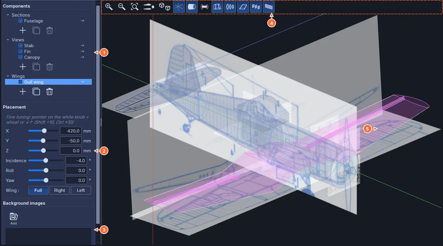
- Components: the tree of elements, by family.
- Placement of the selected element.
- Background images of the assembly: its free images (chapter 12).
- The 3D view toolbar.
- The mock-up. The mouse works as everywhere: mouse wheel to zoom, middle button or Alt + left button to rotate, right button to pan. The selected element is drawn in magenta.
11.2 The components
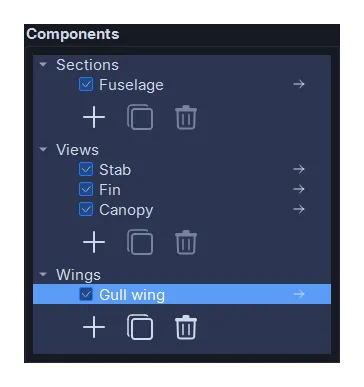
The tree has three families, in the order of the tabs: Sections, Views, Wings. Under each one, one row per placed element, with:
- a box that shows or hides it in the mock-up;
- its name (a double-click renames it, like right-click ▸ Rename…);
- an arrow → that opens the element in its editing tab.
Each family ends with three buttons: + creates a new element of this family (a name is asked for; the button is active even when the family is empty), Duplicate places a copy of the selected element (the same element, placed a second time: a second fin, a second float; the copy is offset by 50 mm) and the trash can deletes, after confirmation, only the selected placement when the element is placed several times, otherwise the element itself (if it has transferred documents, you choose to delete them too or to keep them as free documents).
Clicking a row selects the element, in the tree and in the mock-up; clicking the selected row again, or a family title, deselects it. The selection is kept when you change tabs.
11.3 Placement
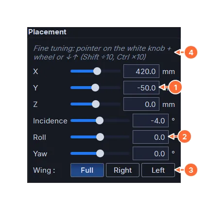
- The X, Y, Z position of the element in the mock-up, in millimeters: X along the aircraft, Y in height, Z across (the coordinate system of the machine table, that of the axes of the 3D view). The mouse wheel acts on these sliders, for fine tuning (item 4); the field on the right gives the exact value.
- The incidence (the rigging angle, a rotation about the transverse axis), the roll (a rotation about the longitudinal axis) and the yaw (a rotation about the vertical axis), in degrees. A wing pivots about the leading edge of its first rib. The incidence and the yaw apply to the element as it is drawn, and the roll last: it carries them along with it. A stabilizer drawn upright in the Views tab, like a fin, then laid flat by a 90° roll, therefore gets its incidence from the yaw: with a 90° roll, a positive yaw tilts it the opposite way to a positive incidence on a wing; with a −90° roll, the same way.
- For a wing: show the full wing, the right half or the left half.
- The fine-tuning reminder, at the top of the frame: pointer on the white knob of a slider, then mouse wheel, or the ↓ ↑ arrows once the knob has been clicked. Each notch of the wheel or each arrow press changes the value by one unit (1 mm or 1°), with Shift by a tenth, with Ctrl by ten, as in the field on the right; Page Up and Page Down do ten times more.
A sections or views element also has a display choice: for sections, the loft (the skin) or the contours only; for views, the solid, the solid and the curves, or the curves only.
Each placement change shows at once; a slider drag counts as only one step in the undo history, like each arrow press or each notch of the wheel. The view keeps its zoom and its framing while you place an element: a change of placement, selection or visibility, Undo and Redo do not reframe it. It is reframed by the fit-to-view button, the view buttons and the axes button, and when the mock-up is rebuilt: returning to the tab, creating, duplicating or deleting an element, opening a file.
11.4 The 3D view

- Zoom in, zoom out, fit to view.
- The view cycle (top, side, front) and the isometric / perspective 3D view.
- The axes.
- The surfaces of all the elements.
- The hollows (the inner surfaces of the sections elements).
- The wings’ structural elements (spars, hinges, sheeting, kerf grooves), as the Wing tab draws them.
- The contours (all the lines).
- The overall outline (silhouette, CAD style).
- The images of the elements’ locations: sections, side and top views, the wings’ plan views. Those of all the displayed elements stay visible when an element is selected: you can place one from the image of another.
- The free images: those of the elements, which follow their element, and those of the assembly, always shown.
The images of an element, the location images as well as the free images, follow it when it is placed: each one keeps, relative to it, the place it has in the element’s tab, so that an element fitted to its plan in that tab stays fitted in the mock-up. The plan view of a wing is thus at the same distance under the wing as in the Wing tab (the vertical position of the blocks page), and changing the dimensions of the wing slides it under this plan without moving the plan, as in the Wing tab (chapter 8). This is one of the exceptions to the principle that separates images from geometry (chapter 12).
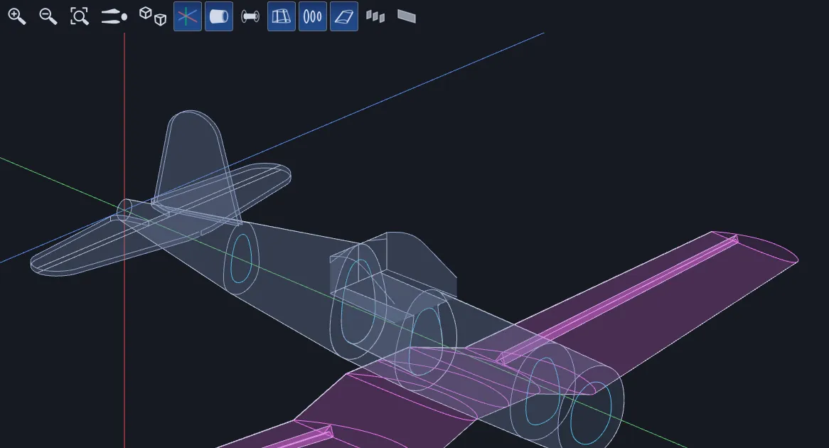
A views volume with an open curve appears as a ribbon. Hiding the surfaces and keeping the overall outline gives a wireframe view.
11.5 What the assembly saves
The placements, the copies and the visibility of each element are saved in the .hw4x file. When a file that contains elements is opened, the software opens on this tab. The tab has its own history for Undo and Redo (chapter 3), reset when an element is created or deleted.