The Views tab builds a volume from two silhouettes: a block is cut a first time following one view (from the side, for example), then turned a quarter turn and cut following a second view (from above). The resulting volume is the intersection of the two cuts: a canopy, a nose, a stabilizer, a fin, a float… anything that two views describe well. Each pass is a two-axis cut (both sides of the wire follow the same path).
The screenshots show the canopy and the stabilizer of the Corsair (Corsair F4U.hw4x), drawn over a reference plan, and, for the stations, the element that the + button creates.
10.1 The Views tab
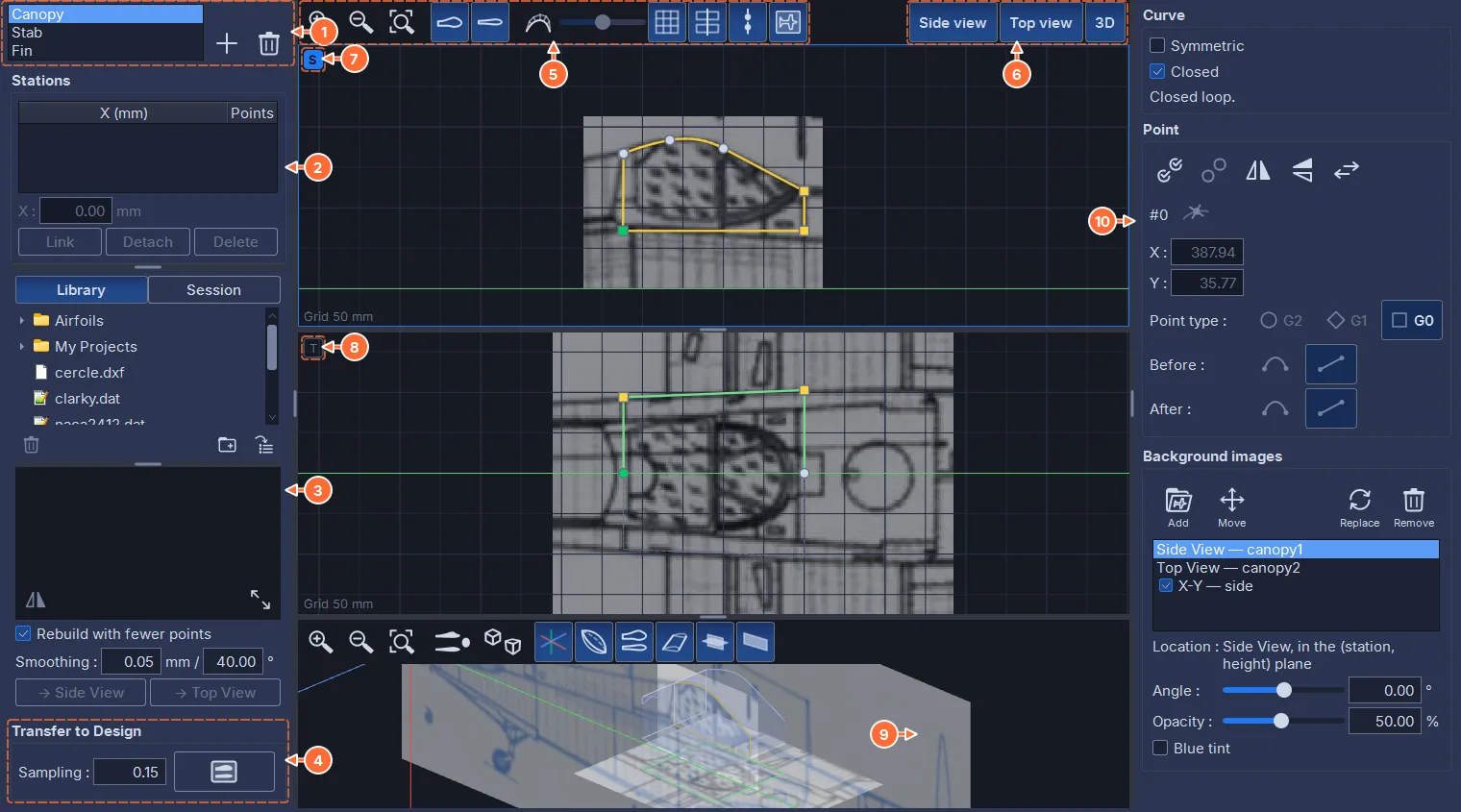
- The list of the workspace’s views elements (the canopy, the stabilizer, the fin), + and the trash can.
- The stations: X positions shared by points of both views (section 10.5).
- The profile library, to import a curve (section 10.6).
- Transfer to Design: the sampling (the discretization tolerance of the curves for the cut and the 3D view, in millimeters; 0.15 mm by default) and the transfer button for the two views (section 10.8).
- The banner of the 2D editors (section 10.2).
- Side view, Top view and 3D: the panes shown in the center.
- The Side view pane, the editor of the side view, marked by the S badge.
- The Top view pane, the editor of the top view, marked by the T badge.
- The 3D view of the volume.
- The right page of the active view.
The two views are drawn in the same longitudinal coordinate system: the horizontal axis is the axis of the volume, the station, common to both views. The side view is drawn in the (station, height) plane, the top view in the (station, width) plane. Like a wing profile, whose leading edge is on the right, a fuselage is drawn with its nose on the right, toward increasing stations. The block stays at the same place in X between the two passes: this is what guarantees that the two cuts overlap.
The list’s + creates an element (a name is asked for): a small 300 mm glider fuselage. Its side view is a closed loop of 8 points, the flat rear on the left and the nose on the right; its top view is a symmetrical half curve of 6 points. It opens ready to work: the three panes shown, the two 2D views unlinked, the stations visible, each view framed.
The left column collapses completely when its handle is dragged to the edge of the window; dragging it again brings it back. The handle between the Stations frame and the library sets how they share the space; dragged all the way down, it collapses the whole library.
10.2 The banner and the panes

- Zoom in, zoom out, fit to view: they act on the active view. When the two views are linked, fit to view frames both curves over the same extent in X, each centered vertically in its pane.
- Side view curve and top view curve: one button per view shown, each with its icon (the side profile, the top view). Released, it hides the curve and locks its editing, so that only the background image to trace is visible.
- The curvature comb of the active view and its scale (as in Sections, section 9.3).
- The grid.
- Link the two 2D views: the same zoom and the same left-right framing for both views, so that the stations match on screen; each view keeps its own vertical framing. On by default, the button is grayed out when only one 2D view is shown.
- Stations: the station lines in both views (section 10.5).
- Image: the background image of the active view, in the 2D editor only; the 3D view has its own button.
- Side view, Top view, 3D: each button shows or hides its pane.
The three pane buttons are independent. The panes shown are always arranged in the same order, from top to bottom: Side view, Top view, then the 3D view. Two 2D views one above the other is the layout of a two-view drawing: the stations line up from one view to the other. Hiding everything leaves the center empty; a click brings a pane back. Each combination of panes keeps its own splitter position. With no 2D view shown, only the pane buttons remain in the banner.
The active view is the one that the right page, the banner buttons and the status bar follow. A click in a 2D pane makes it active: it then has a thin colored frame, and its badge, S or T in the upper left corner, is filled; that of the other pane is only outlined. Hiding the active pane makes the other view active.
The status bar gives the length of the volume, its height H and its width W, and the number of selected points; the mouse button, on its left, opens the Keyboard and mouse window, which sums up the editors’ gestures (chapter 3).
10.3 The two curves
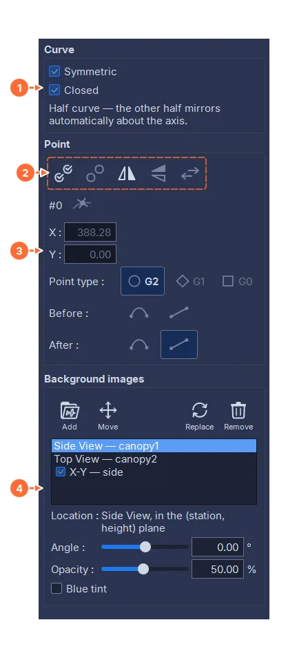
- Curve: the Symmetric and Closed boxes, and a line that describes the state of the curve.
- Select all, deselect all, mirror horizontally, mirror vertically (grayed out on a half curve) and Reverse the direction.
- Point: the same tools as in Sections (section 9.4).
- The background images (chapter 12): the Side View and the Top View, the plan or the photo to trace behind each view, then the free images. Move on a view row makes that view active, then the image is dragged in its editor.
The two boxes are independent and always visible; they give four states, which the line under the boxes recalls:
| Symmetric | Closed | State | Line shown | Cut | 3D view |
|---|---|---|---|---|---|
| no | yes | free loop | “Closed loop.” | one closed pass | solid |
| no | no | open curve | “Open curve: the wire enters at the green point and leaves at the last point.” | one open pass, from the first point to the last | ribbon |
| yes | yes | closed half curve | “Half curve — the other half mirrors automatically about the axis.” | one closed pass | solid |
| yes | no | open half curve | “Open half curve: the wire enters and leaves at the free end and its reflection.” | one open pass, from the free end to its reflection | ribbon |
- A free loop is drawn whole: a side silhouette, a fin.
- An open curve does not join its last point to its first: the pass crosses the block from one end to the other (a through cut, a hull profile open at the top). Point #0, in green, is the one where the wire enters.
- A closed half curve is only drawn above the axis, its two ends on the axis; the other half is mirrored automatically (a symmetrical top view).
- An open half curve joins its reflection at only one end, on the axis; the other end is free: a part one end of which is the face of the block.
Checking or unchecking a box always follows the same principle: an existing point does not move; what is added is neutral (a straight segment, or a point placed exactly where the curve crosses the axis); a change that would lose part of the drawing asks first; an impossible change is refused with its reason, and the box stays as it was. Each change is undone in a single step.
- Unchecking Closed removes a single segment: the one that joins two selected neighboring points, otherwise the closing segment. On a half curve, it is an axis end that goes, with its segment: the selected one, otherwise the left one; its neighbor becomes the free end.
- Checking Closed joins the two ends with a straight segment; the two joined points become sharp corners, so the outline does not change. A last point placed on point #0 merges with it. A closed curve needs at least three points. On a half curve, the free end goes straight down to the axis: an axis point is added directly below it, joined by a straight segment.
- Unchecking then checking Closed again without changing anything in between gives back exactly the previous curve.
- Unchecking Symmetric turns the reflection into editable drawing, without changing the shape: a closed half curve becomes a loop, an open half curve an open curve. Nothing is lost.
- Checking Symmetric cuts the drawn curve where it crosses the axis (a sharp-corner point is created there) and keeps the part above the axis, which must be in one piece. When the other side is not the exact reflection of the first, a question offers Keep the top half or Keep the bottom half, or to give up; the discarded side can then be recovered with Undo (Ctrl+Z). The change is refused, with a message, when the curve does not cross the axis (bring it across the axis: select all, then move), when several separate pieces are above the axis, or when the part of an open curve above the axis meets the axis at both ends (check Closed first).
The two boxes are grayed out as long as the curve is hidden (the view’s curve button, in the banner).
Reverse the direction reverses the order of the selected points (each run of consecutive selected points is reversed in place), or that of the whole curve when nothing is selected. An open curve then starts at its other end: that is where the wire enters. A loop keeps its point #0 and runs the other way, which does not change the cut: the transfer puts all loops back in the clockwise direction. On a half curve, the direction is set by the axis: the button is grayed out when nothing is selected, and a selection that contains a point of the axis is refused. The button works with no selection or on at least two selected points.
10.4 The 2D editor
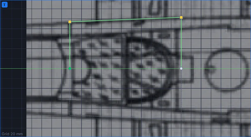
The 2D editor works like the segment editor (section 9.3): a click takes a point alone, Ctrl + click adds or removes it, drag, double-click, Delete, selection boxes, the S, T, A and D keys, Alt + drag, mouse wheel. What is specific to it:
- a point dragged to within 3 pixels of the axis lands exactly on it; Alt during the drag suspends this snapping;
- a simple gesture (a click on a point, a box, a click on empty space) also deselects the other view shown: a point forgotten in the other view no longer follows the drag in X. With Ctrl or Shift, the selection of the other view stays; a hidden view keeps its own;
- on a half curve, the ends stay on the axis (they only move in X), the other points stay above it, and the mirrored half is drawn dotted;
- the type of an axis point is set like that of the other points: in G2 or G1, the curve meets the axis at a right angle; as a sharp corner, the joint with the reflection is pointed (a pointed nose);
- a loop keeps at least three points; an open curve keeps at least two, and its ends are deleted like the other points; a half curve never loses an axis end and keeps at least one point off the axis;
- Alt + drag enlarges or shrinks a half curve about a point of the axis, so that its ends stay on it; a free curve, about its leftmost point;
- Esc deselects the points of the views shown, even when the right page or the station table has the focus.
10.5 The stations
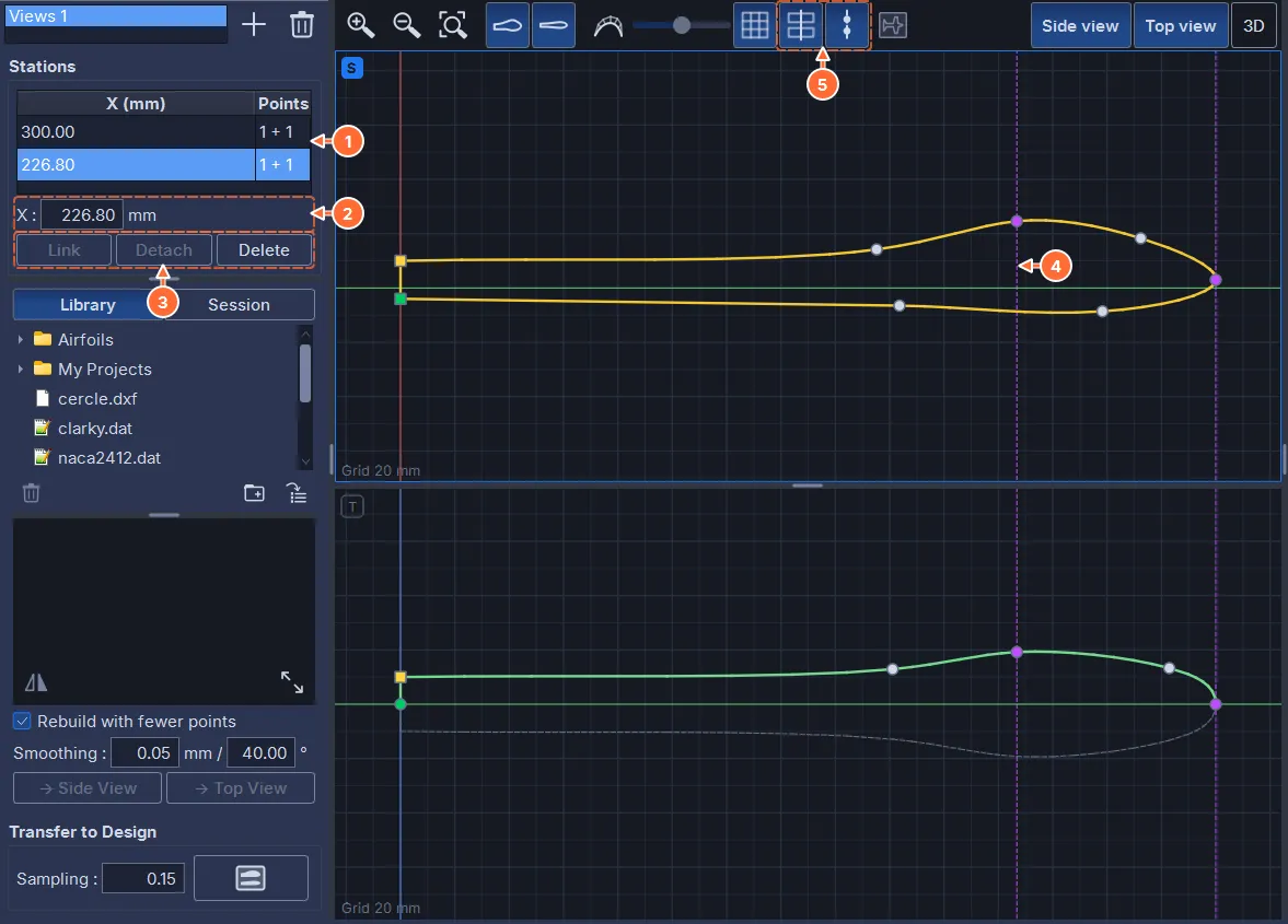
- The station table: the X position X (mm) of each one and its Points (“1 + 1”: one point in the side view, one in the top view). A click selects a station.
- X: the X position of the selected station; changing it moves all its points.
- Link, Detach, Delete.
- A station, drawn as a thin dotted line in both views; its points are violet.
- The banner buttons that link the two views and that show the stations.
A station is an X position shared by points of the side view, of the top view or of both: the nose of a fuselage stays at the same station in the side view and in the top view. Moving a point of a station in X moves the station, and its other points follow. A point belongs to only one station, and a station always has at least two points. Stations are a drawing aid: they change neither the cut, nor the transfer, nor the exports.
- Link, with no station selected in the table, creates a station with the points selected in both views: they take the X of the last point clicked. To select a point in each view: click the point in the first view, then Ctrl + click the one in the other (a plain click would deselect the first). With a station selected, the selected points join it; the station does not move, the points come to it.
- Detach frees the selected points from their station; a station that no longer has two points disappears.
- Delete deletes the selected station; its points stay where they are.
After Link or Detach, no point is selected any more, in any view. Each change to the stations is undone in a single step.
In both 2D views, a station is a thin dotted vertical line, drawn under the curve, and its points are violet (a selected point keeps the selection color, and point #0 stays green). The Stations button of the banner hides the lines. With the two views linked, the lines line up from one view to the other.
When both 2D views are shown, dragging a selection in one view also moves, in X only, the selected points of the other view: X is the only coordinate the two views share. These points were chosen on purpose, with Ctrl or Shift, since a simple gesture deselects the other view. With a single 2D view on screen, the drag only moves what you see.
10.6 Importing a profile
The library in the left column shows the same folder as the one in the Design tab (chapter 4), with its own import buttons.
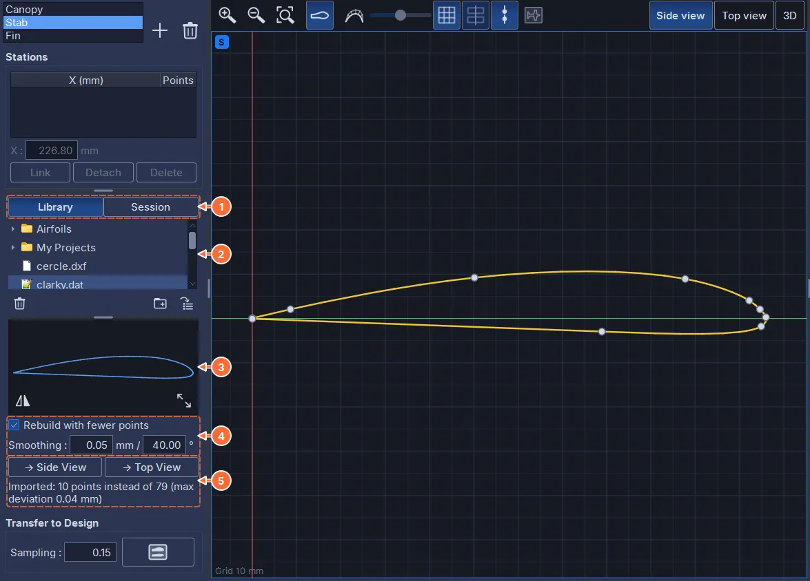
- Library or Session: the files of the library folder, or the profiles of the open project (the Design documents, the outlines of the views, the ribs of the Wing tab, the sections of the segments).
- The file tree.
- The viewer, with its mirror and enlarge buttons; enlarged, the library fills the whole tab.
- Rebuild with fewer points and, below it, Smoothing: the maximum deviation allowed between the rebuilt curve and the file (0.05 mm by default), then the angle from which a point stays a sharp corner (40° by default).
- → Side View and → Top View replace the curve of the view with the selected profile; the line below says what the import did (“Imported: … points instead of … (max deviation … mm)”).
A file that contains several profiles (a DXF with several paths) opens the Select Trajectories window (chapter 4): the chosen paths are chained into a single curve. A project document offers its two sides; two identical sides (a two-axis cut, such as a document transferred from this tab) count as only one profile. DXF and SVG files are read as they are drawn, without the cleanup of aligned points that the Design tab applies on import.
The import replaces the curve of the view in a single undo step, according to these rules:
- Size: a
.dator.corprofile, which has no dimensions, takes the length of the view it replaces; the other formats keep their millimeters. - Position: the leftmost point is placed at the X of the leftmost point of the replaced view, so that the view stays facing the other one. Vertically, a symmetrical shape places its axis on the axis of the view, a
.datplaces its chord line there, and any other shape is centered on it. - Closing: the curve is closed only if the last point of the file falls on the first; it is never closed automatically. A profile with an open trailing edge stays an open curve (checking Closed closes it with a straight segment).
- Symmetry: a shape that is its own reflection about the horizontal line through its mid-height automatically becomes a half curve: closed for a loop, open for an open curve that crosses the axis once.
- Order: a loop starts at its leftmost point and runs clockwise; an open curve keeps the order of the file (the wire enters at its first point; Reverse the direction changes it).
- Points: with Rebuild with fewer points unchecked, all the points of the file, joined by straight segments: the exact outline. Checked (the default), a smooth curve with few points, which stays within the Smoothing of the file; sharp corners stay sharp and straight parts stay straight.
- All the stations of the element are deleted, since the points of the view are all new; the background image of the view stays; the imported view is framed.
10.7 The 3D view
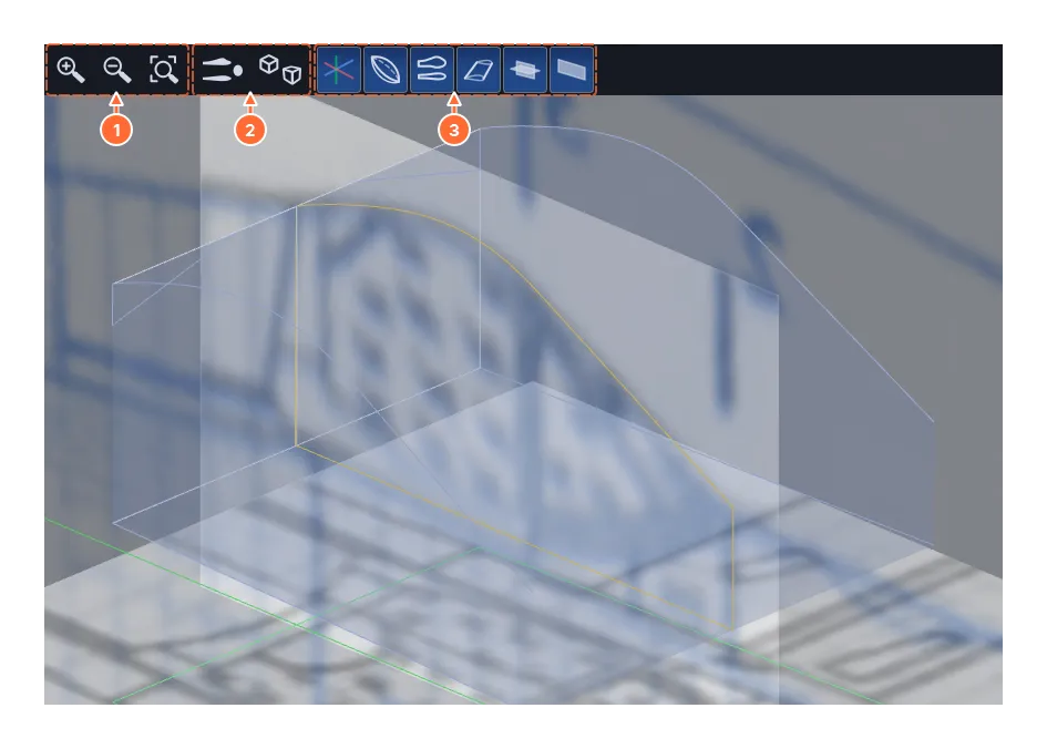
- Zoom in, zoom out, fit to view.
- The view cycle (side, top, front) and Ortho / 3D view.
- The axes; the solid (the intersection of the two passes; an open view gives a ribbon); the curves of the two views in their planes; the overall outline; the images of the two views in their planes; the free images.
The solid shown is exactly what the two passes produce: the upper and lower faces come from the side view, the side faces from the top view, each curve being extruded through the block.
10.8 Transferring the two views
The button of the Transfer to Design frame, to the right of the Sampling field, opens a small window that asks for the first pass: the side view or the top view.
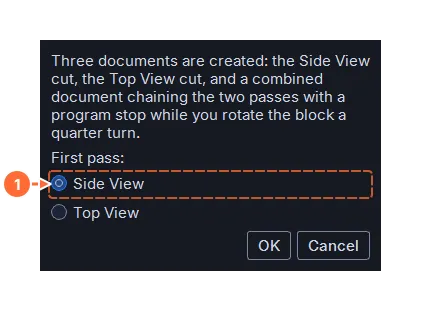
- The view cut first (the side view by default).
Three documents are created in the workspace, V1.1, V1.2 and V1.C for element 1; V1.1 becomes the active document and the Design tab is shown. A new transfer of the same element updates the three documents, after a confirmation that names them.
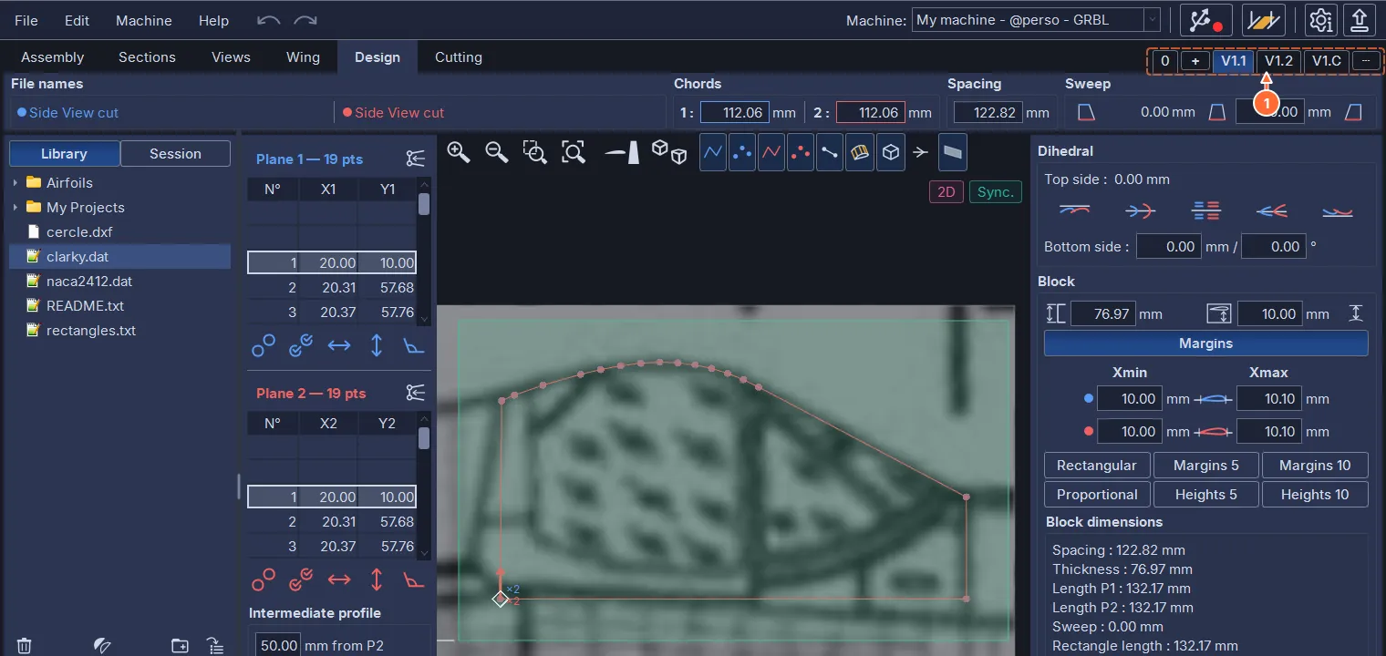
- V1.1 is the cut of the side view, V1.2 that of the top view, V1.C the two passes chained.
The documents open in Design and Cutting like any project.
10.8.1 The V1.1 and V1.2 cuts
Each view becomes a two-axis cut (both sides receive the same path), following the principle of a wing profile:
- a closed curve starts at its leftmost point (the highest one if there are several: the rear of a fuselage whose nose is on the right, like the trailing edge of a profile) and runs clockwise; a closed half curve starts at its point #0, on the axis;
- an open half curve also runs clockwise, from its free end to its reflection; an open curve keeps the order of the drawing (the wire enters at the first point and leaves at the last);
- the cut definition is that of a wing profile: horizontal approach and return from the left, kerf on the left (chapter 5);
- the spacing is the extent of the other view, plus 10 mm on each side; the block has the height of the curve, plus 10 mm above and below.
The two documents describe the same block: same position in X on the machine, same length. The block margins absorb the offset between the two curves: the view that starts furthest to the left has a 10 mm margin, the other a larger margin; on the right, each margin extends to the furthest end of the two views, plus 10 mm.
Each document receives the background image of its view, on its Plane 1 (chapter 12); the element’s free images are not carried over.
10.8.2 The combined document V1.C
V1.C chains the two passes in a single program, each placed exactly as in its own document. After the first pass, the wire leaves the block horizontally and stops 5 mm to the left of its left face: this is a stop point (chapter 4). During the stop, turn the block a quarter turn about its longitudinal axis, the left face staying in place, then restart: the wire reaches, outside the block, the entry height of the second pass and enters the block from the left.
The block of V1.C is the taller of the two blocks, and its spacing the larger of the two. The document receives the images of both views, each under its pass.
10.9 Exporting the outlines
File ▸ Export ▸ Export Side View outline… and Export Top View outline… save the outline of one view of the displayed element, as .dat or .dxf depending on the extension given. The outline is the one the transferred document receives (same starting point, same direction): the file can be imported again into Design, or join the library to serve as a profile in the Wing tab. The proposed name is that of the element followed by _view1 or _view2, in the library folder. A .dat has no dimensions: the size comes back from the plane it is imported into; a .dxf keeps the millimeters.
These two entries are only active in the Views tab, when the view has at least two points. Export requires an active license (chapter 16).