The Sections tab builds a volume slice by slice: a fuselage, a fairing, a hull, a nacelle. The volume is cut into successive segments; each segment is a sheet of material of a given thickness, whose two faces you draw: the left section and the right section. The wire, guided by the two sections, cuts the sheet into a segment whose surface runs from one to the other. The segments glued end to end form the volume.
Sections are drawn freehand, as smooth curves with a few points, or imported from the profile library; they can be hollowed (an inner section). The tab then nests the segments on sheets, several per sheet, and creates one cutting document per sheet.
The screenshots show the fuselage of the Corsair (Corsair F4U.hw4x, five segments) and, for nesting on sheets, that of the Caudron (Caudron C450.hw4x, twenty segments).
9.1 The Sections tab
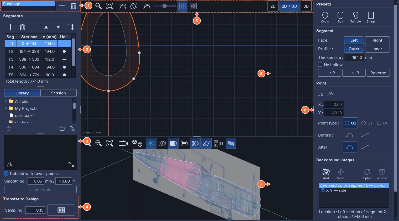
- The list of the workspace’s sections elements, + and the trash can.
- The segments of the active element (next section).
- The profile library, to import a section (section 9.5).
- Transfer to Design: the sampling (the discretization tolerance of the curves for the cut and the 3D view, as a chord deviation in millimeters; 0.15 mm by default) and the sheets button, which opens the nesting window (section 9.9).
- The banner of the 2D editor and the choice of the 2D / 2D + 3D / 3D panes.
- The 2D editor of the active section.
- The 3D view of the volume.
- The right page: the segment, the section, the point, the background images.
The status bar shows the dimensions of the section (width, height, station) and the number of selected points. The mouse button, on its left, opens the Keyboard and mouse window, which sums up the editor’s gestures (chapter 3).
The left column collapses completely when its handle is dragged to the edge of the window; dragging it again brings it back. The handle between the Segments frame and the library sets how they share the space; dragged all the way down, it collapses the whole library.
9.2 The segments
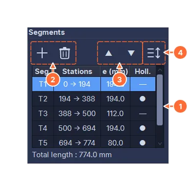
- The table: the segment number, its stations (the positions of its two faces along the volume, the first face of the first segment being at 0), its thickness e and a hollow indicator. Clicking a row makes the segment active; so does clicking the segment in the 3D view (section 9.6).
- Add inserts a segment after the selected segment (after the last one when none is selected): its left face takes over the right face of the previous one, to ensure continuity; Delete removes the selected segment (down to zero segments).
- ▲ and ▼ move the segment in the list. With no segment selected, Delete, ▲ and ▼ are grayed out.
- Reverse the list reverses the order of the segments.
The stations are not entered: they are deduced from the thicknesses. An element can have just one segment (a single sheet with two different faces) or several dozen.
9.3 The section editor
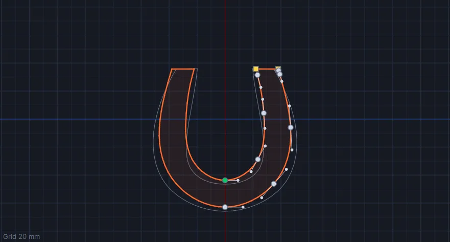
A section is a half curve: the volume is symmetrical, so only the right half is drawn, from top to bottom, and the software mirrors it. The two ends are on the symmetry axis and stay there (they only move vertically); the curve meets the axis at a right angle, unless the point is a sharp corner (a keel or a ridge). The horizontal axis marks the reference line of the volume: heights are absolute, and a section can be higher or lower than the previous one.
The gestures:
- dragging a point moves it: a point that was not selected moves alone, a point of the selection takes the other selected points along; Shift + Ctrl + drag moves the selection starting from anywhere; a double-click on the curve inserts a point; Delete erases the selected points (a section keeps at least three points), after which no point is selected any more;
- selection follows the rules of the Design tab’s Points mode (chapter 4): a click on a point selects it alone, which lets you go from one point to another without deselecting; Ctrl + click adds or removes it without touching the others (the cursor shows ±); Shift + click adds the range from the primary point (the last one clicked, the one the right page edits), Ctrl + Shift + click removes that range; a box replaces the selection (Shift + box adds, Ctrl + box removes); a click on empty space deselects, like Esc; Ctrl + A selects everything; the selected points are painted in the accent color;
- Shift during the move constrains it to the horizontal or the vertical; Alt + drag (Alt pressed before the click) enlarges or shrinks the selection (or the whole section) about the axis;
- S, T, A change the type of all the selected points (see the right page); D toggles the segment that follows the point between curve and line, when a single point is selected;
- the mouse wheel zooms, the right or middle button pans the view.

- Zoom in, zoom out, fit to view.
- Tangents: the handles of the curve.
- Other section: the opposite face of the sheet as a ghost, to draw one facing the other.
- The curvature comb, and its scale: the teeth show the curvature along the curve; an even curve gives an even comb, and a bump shows up at once.
- The grid (the step adapts to the zoom).
- The reference image of this section (section 9.7).
- The panes: the 2D editor alone, the editor above the 3D view, the 3D view alone.
9.4 The right page
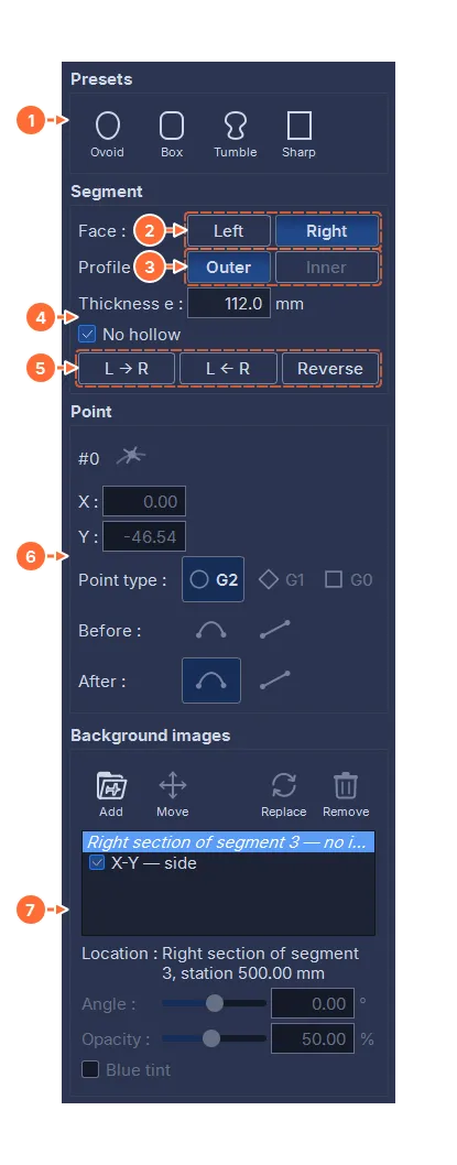
- The presets: four starting shapes, ovoid, rounded box, tumblehome (sides curving inward), sharp box.
- Face: Left or Right, the section being edited. A click on a segment of the list opens the face it shares with the previously selected segment.
- Profile: Outer (the outline) or Inner (the hollow). The two curves are edited separately; the inner section must not go outside the outer one, and a warning says so.
- Thickness e of the segment (the thickness of the sheet) and No hollow: the inner section is ignored for this segment, but kept; unchecking the box restores it.
- Continuity: L → R and L ← R copy into the edited face the selected profile (outer or inner) from the neighboring face, that of the adjacent segment or the other face of the same segment depending on the arrow; the tooltip names the source. Reverse swaps the selected profile between the two faces of the segment.
- Point: the number of the selected point and, to its right, the button that deletes it; its X and Y coordinates; its point type: G2 (smooth, the curvature is continuous, the default), G1 (smooth, only the tangent is continuous, which isolates the point from its neighbors), G0 (sharp corner); the segment before and the segment after the point, as a curve or a line. With several points selected, the number is that of the primary point (the last one clicked), followed by the number of selected points; X and Y show the primary point, and a value entered moves it; two buttons, which only appear at that moment, say what the other selected points do: Translation (the default), they follow by the same offset; Destination, they all take the value entered, which lines them up on the same X or the same Y. In Destination, Enter on the displayed value applies it too, without retyping it: handy after a value entered by mistake in Translation. Each point keeps its constraint (an axis point stays on the axis). The type buttons apply to all the selected points; a button only appears pressed if all these points have the same type. The before and after segments concern a single point: they are grayed out as soon as more than one point is selected (on a closed curve, the first and the last point are one and the same).
- The background images: the image of the edited section, then the free images (section 9.7 and chapter 12).
Items 2 to 5 form the Segment frame. The face and the profile it designates are also the ones that an import from the library replaces (next section).
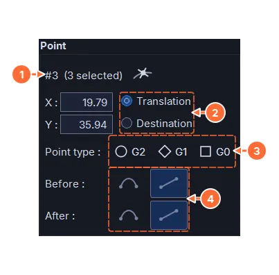
- The number of the primary point (the last one clicked) and the number of selected points, followed by the button that deletes them.
- Translation or Destination: what the other points do when a value is entered in X or in Y.
- The types: no button is pressed here, because the three points do not have the same type; a click gives the chosen type to all three.
- The before and after segments, grayed out: they concern only one point at a time.
A section closed on a straight line (a flat bottom, a vertical side) is drawn with straight segments; the joint between a line and a curve stays tangent.
9.5 Importing a profile
The library, under the Segments frame, shows the same folder as the one in the Design tab (chapter 4); the Library / Session switch also offers the profiles of the open project (section 10.6). Its import button replaces the profile being edited with the selected profile.
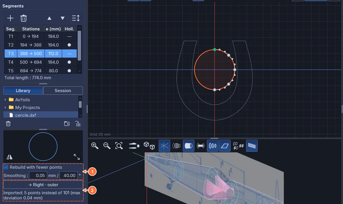
- Rebuild with fewer points and Smoothing, as in the Views tab (section 10.6): checked (the default), a smooth curve with few points, which stays within the smoothing of the file; unchecked, all the points of the file joined by straight segments.
- The import button, named after the profile it replaces, that is, the face and the profile chosen in the Segment frame (”→ Right · outer”); below it, what the import did (“Imported: … points instead of … (max deviation … mm)”).
A section is a half curve: the imported profile is reduced to one half.
- The profile is first closed (an open profile is closed from its last point to its first), then split by a vertical axis placed in the middle of its width.
- A symmetrical shape gives its right half. For any other shape, a question asks which one to keep: Left half, mirrored to the right of the axis, or Right half.
- The kept half must run from one point of the axis to the other in one piece; otherwise (a notch that crosses the axis, for example), the import is refused with a message.
- Size and position: the millimeters of the file are kept; a
.dator a.cor, which has no dimensions, is set to the width of the section it replaces. The heights are those of the file; the axis is placed on the axis of the section.
A file that contains several profiles opens the Select Trajectories window (chapter 4). The import is undone in a single step; the other face, the other profile and the image of the section do not change.
9.6 The 3D view
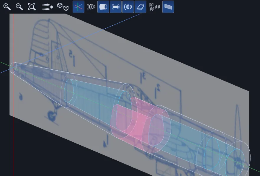
Between two sections, the surface is ruled: the surface swept by a straight wire. The view therefore shows exactly what will be cut, segment by segment, a little angular where the volume turns quickly; adding segments is enough to refine it.

- Zoom in, zoom out, fit to view.
- The view cycle (side, top, front) and Ortho / 3D view.
- The axes.
- Current segment only.
- The envelope: the skin between the sections; that of the active segment is tinted, and the active section is circled in magenta.
- The inner surface (the hollows).
- The section contours.
- The overall outline (silhouette, CAD style).
- The section images in 3D: none, that of the active section, all (a button that cycles).
- The free images.
A click on a segment in the 3D view makes it active, like a click on its row in the table: the row is selected, and the 2D editor, the right page and the coloring of the view follow. A click on empty space deselects the segment: no row is selected, the 2D editor is empty, the right page and the library import are grayed out, the 3D view no longer colors any segment (with Current segment only, it shows them all) and the status bar gives the dimensions of the whole element. Clicking a segment, in the view or in the table, selects it again; so does a change to the list (addition, deletion, move, reversal) or an undo. The click works in every orientation; in front view, it takes the nearest section.
9.7 The background images
Each section can have its own image (the drawing of the section at this station, a photo), drawn behind the curve for tracing. It is the first row of the Background images frame of the right page, named after the edited section (“Right section of segment 3”); it follows the chosen segment and face. Add picks the image from the image bank, Replace puts another one in its place, Move moves it (then drag in the editor; the mouse wheel zooms the view), Remove removes it; the angle, the opacity and the blue tint are set below. The scale is the one calibrated in the bank (chapter 12). An added segment does not take over its neighbor’s image: an image belongs to a station.
The Image button of the banner shows or hides it in the editor; in the 3D view, it is the cycle button of the 3D toolbar that shows the section images in their planes.
9.8 Cutting a segment
Each segment is cut out of its sheet with the same route, set once and for all:
- the wire enters through a vertical lead-in above the section, on the axis;
- it goes around the outer section counter-clockwise;
- if there is a hollow, it reaches the inner section through a bridge on the axis, goes around it the other way, and comes back through the same bridge;
- it leaves through the lead-in.
The bridges and the lead-ins are junction paths (with no kerf compensation), so the hollow cuts the part at only one point, on the axis, where the two passes of the wire cross in a tiny spike that serves as a mark for gluing. The wire travels the two faces at the same time, synchronized by their arc length: the necessary synchronization points (the lead-ins, the bridges) are placed on transfer. Kerf compensation, for its part, is done in the Cutting tab with the chosen material; the segments are transferred at their nominal dimensions.
9.9 Nesting on sheets and transferring
The button of the Transfer to Design frame, to the right of the Sampling field, opens the nesting window: the segments are placed in rows on sheets of the required thickness, within the limits of the active machine’s useful zone, and each sheet becomes a cutting document.
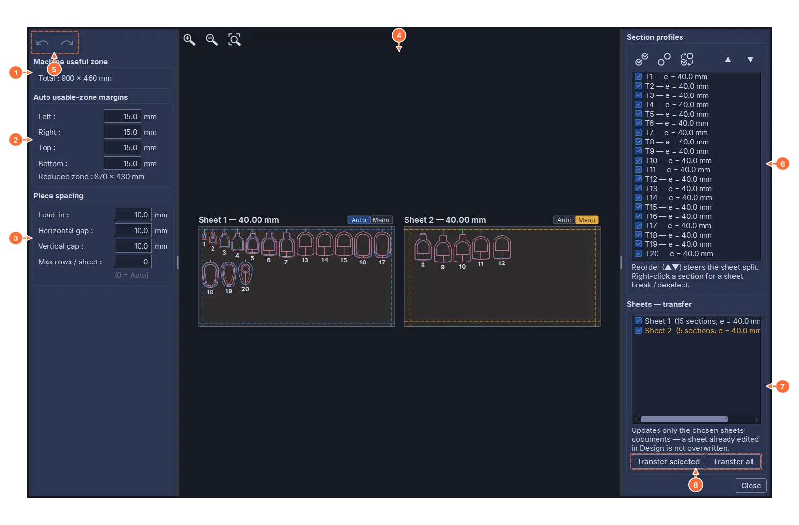
- Machine useful zone: the travel of the active machine (500 × 200 mm when no machine is defined).
- The margins of the useful zone for automatic nesting.
- Piece spacing: the lead-in (the height of the wire entry above each piece), the horizontal and vertical spacing between pieces, and the maximum number of rows per sheet (0 = as many as the height allows). No kerf margin: the pieces are nested at their nominal dimensions, and the kerf is compensated at cutting time.
- The preview: each sheet with its numbered segments, the useful zone, the wire path; the mouse wheel zooms, the right button pans. Each sheet carries an Auto / Manu button: in manual mode, the pieces are moved one by one with the mouse (the bottom, the left and the right are free, the top keeps the lead-in), and the sheet is no longer rearranged.
- Undo and redo, specific to the window.
- Section profiles: the list of segments, checked to be nested, in the nesting order (▲ ▼ change it; right-click forces a new sheet from a segment).
- Sheets: the list of resulting sheets, with the number of segments and the thickness of each; segments of different thicknesses go on different sheets.
- Transfer selected creates or updates the documents of the checked sheets; Transfer all replaces all the element’s documents (after confirmation).
The nesting settings are saved with the element. The documents are named S1.1, S1.2… (element 1, sheet 1, 2…). Each document is a project with two paths: side 1 receives the left faces, side 2 the right faces, and the spacing is the sheet thickness; the block is the machine’s useful zone, with its margin; the approach is set from the left and the return from the top; the kerf side is preset to right, with the variable algorithm. The reference images are not carried over into the sheet documents: a sheet carries several segments side by side, and their images would pile up.
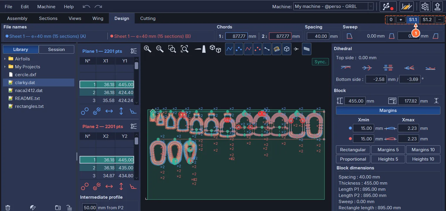
After the transfer, the software reminds you that the synchronization must be redone and puts Design in Sync. mode, with the minimal synchronization points already selected: run the synchronization (chapter 4), check, then go to Cutting.