Vectorization turns an image into paths: a logo, lettering, a line drawing, a cut-out silhouette. The principle is simple: the image is reduced to black and white by a threshold, the outline of each black area is traced, then smoothed and split into straight segments and curves, with the sharp corners kept. The result is exported as DXF or imported directly into a plane of the Design tab.
13.1 Opening the Vectorization window
File ▸ Vectorization…, from any tab, or the vectorization button in the middle of the row of buttons under the file tree of the Design tab’s library (chapter 4); the libraries of the Sections, Views and Wing tabs do not have this button. The window opens over the main window and has two modes, Modify and Vectorize, at the top of the right column.
13.2 Editing the image
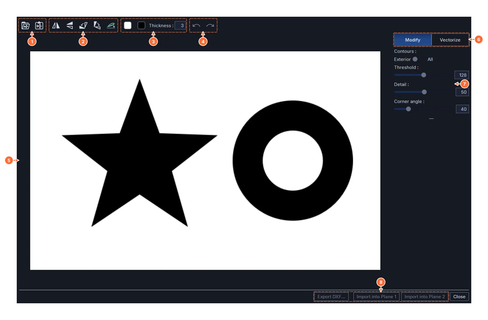
- Import an image file, or paste the image from the clipboard (always available, in both modes).
- Horizontal flip, vertical flip, rotation by −90° and by +90°, and level: click two points of a line that should be horizontal, and the image rotates by that much.
- The two pens, white and black, and the thickness of the stroke: a white stroke opens a slit in a shape (to reach an inner area with a single path, or to separate two shapes that touch), a black stroke adds material (to close an outline, to join two strokes). A stroke is drawn in two clicks.
- Undo and Redo for the strokes (Ctrl+Z, Ctrl+Y).
- The working image; the mouse wheel zooms, the right button pans.
- The two modes.
- The vectorization settings, active in Vectorize mode.
- Export DXF…, Import into Plane 1, Import into Plane 2, Close.
The sharper and more contrasted an image is, the better it vectorizes: a black drawing on a white background, a cut-out photo on a plain background. Gray areas, shadows and gradients give unstable outlines; a pass through a photo editor (contrast, threshold, eraser) removes them before the import.
13.3 Vectorizing
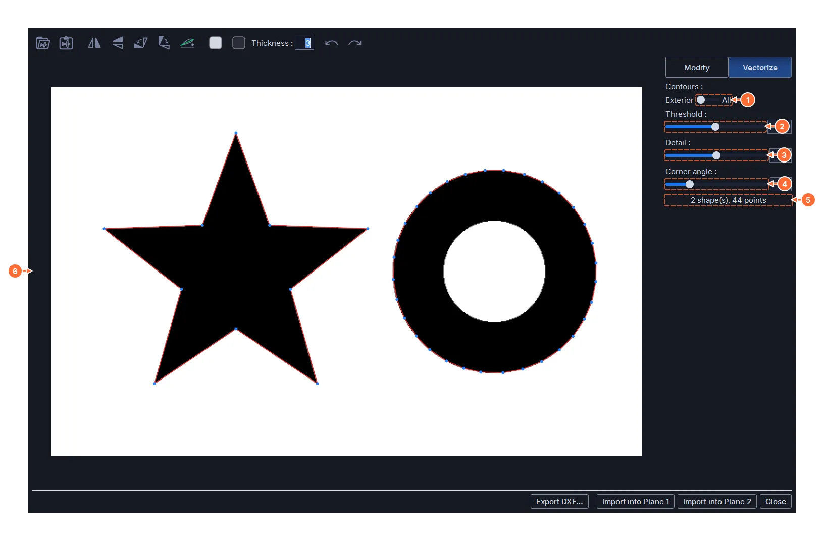
Vectorize mode shows the image in black and white and the path in red on top of it, with its corners in blue. Each setting recalculates the path at once:
- Contours: Exterior keeps only the outer outline of each shape; All adds the inner outlines (hollows, the holes in letters).
- Threshold: the limit between black and white, from 1 to 254; on entering the mode, it is set automatically to the best separation of the image (Otsu’s method). Lowering it thickens the shapes, raising it thins them.
- Detail: from a smooth, light outline to a tight, detailed one; it sets both the smoothing of the curves and the simplification tolerance.
- Corner angle: the angle from which a change of direction is treated as a corner (a sharp vertex, at the intersection of the two edges) rather than as a curve.
- The number of shapes and points obtained.
- The result: the red outline and the corners in blue.
The outlines follow the edges of the pixels with sub-pixel precision: an image a few hundred pixels across is enough for a logo; a higher resolution gives smoother curves.
13.4 Exporting or importing the result
- Export DXF… writes a DXF file with one polyline per shape (a license is required, chapter 16).
- Import into Plane 1 and Import into Plane 2 place the result directly in the active document of the Design tab, like an imported profile: if there are several shapes, the Select Trajectories window (chapter 4) asks which one to take, or which ones to chain. The window closes and the Design tab is shown.
In both cases, the result is scaled to a width of 100 mm, like a .dat profile; it is then given its real dimensions with the chord or the stretch in Design. An image vectorized into Plane 1 alone gives a two-axis cut; two different images on the two planes (lettering that changes from one face to the other) give a four-axis cut, to be synchronized.
The image itself is not kept in the project. To see it behind the imported path, add it to the image bank (chapter 12) and place it as a background image of the document in Design (chapter 4).