6.1 Where the settings live
For HotWire4X, a machine is the full set of settings that describe a cutting machine: its geometry, its travels, its motors, its electronic interface, its margins and its procedures. Machines are saved in the machines.json file of the Datas folder of the data folder (chapter 2). The machine in use is remembered: at the next launch, the software picks it up again.
The active machine is chosen in the Machine list of the toolbar. Each machine appears there in the form Name - @pseudo - GRBL or - IPL5X: the pseudo is a short identifier that also serves as the context of the materials (chapter 7); the interface family is fixed for the session (it is chosen on the startup screen, chapter 2).
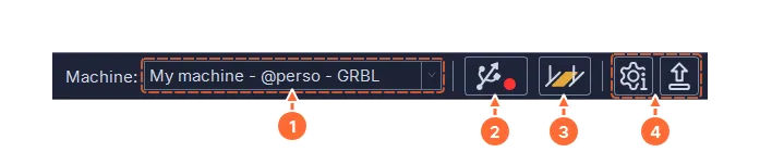
- The active machine.
- Find interface and its status dot (see below).
- Machine configuration, the window described in this chapter.
- The software settings (chapter 3) and the return to the startup screen.
At the top of the list come read-only templates: Default GRBL, Default IPL5X, Mega 2560 RAMPS, BTT SKR Pico v1.0. Each one carries the settings of a known electronic board running the HotWire4X firmware, and the geometry of a reference machine; a tooltip on each template describes it. A template is never modified: it is duplicated.
6.2 Creating a machine
The Machine Configuration window opens with the Machine configuration button of the toolbar or with the Machine ▸ Machine configuration… menu. It has two phases.
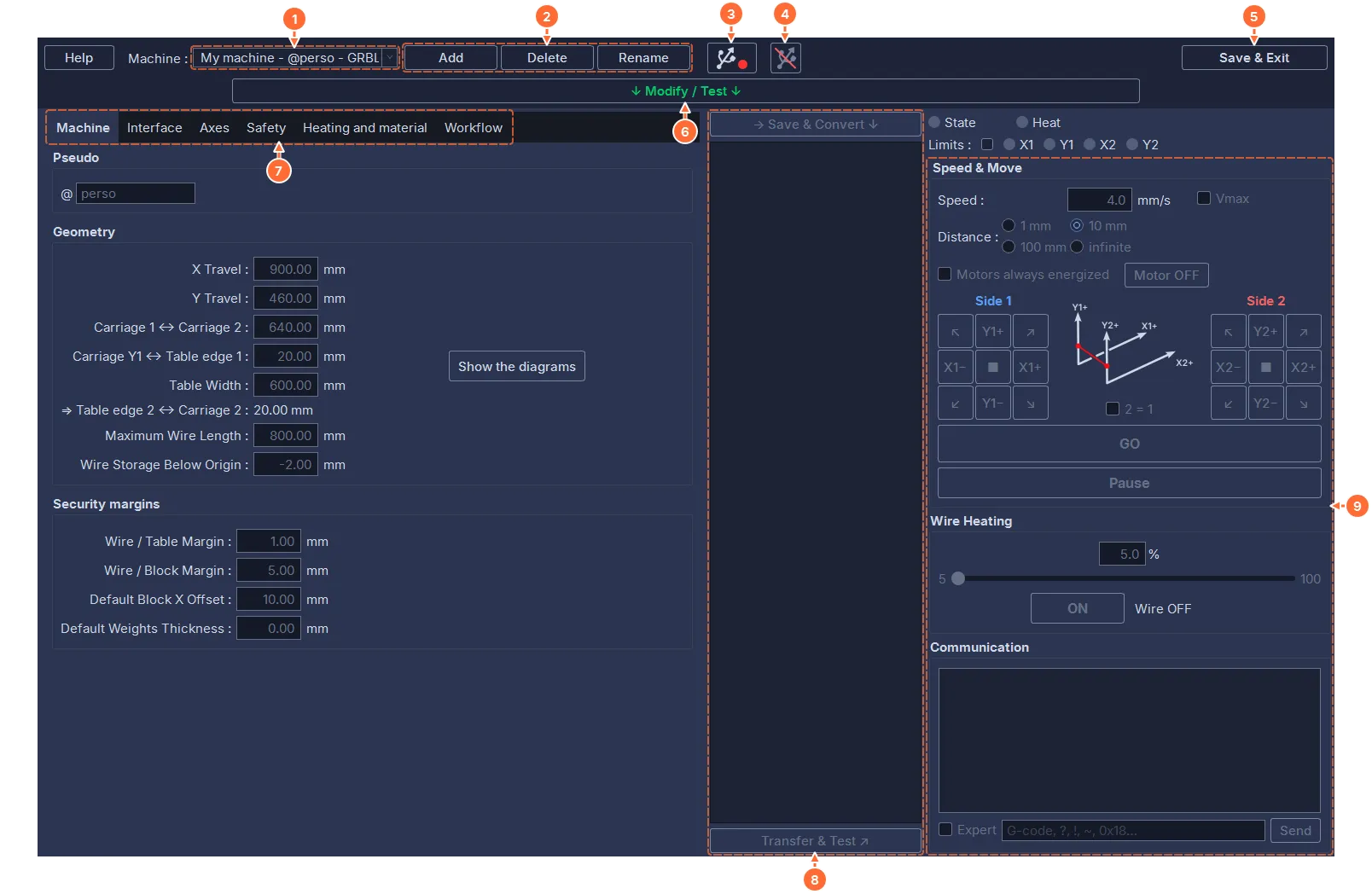
- The list of machines: templates, then the user’s machines.
- Add creates a copy of the displayed machine under a new name (16 characters at most); Delete and Rename act on a user machine.
- Find interface and the status dot, as in the toolbar.
- Release the port: hands the USB port over to another program without closing HotWire4X (see below).
- Save & Exit: saves, makes the displayed machine active, closes.
- Modify / Test: switches to the second phase.
- The six parameter tabs.
- The conversion column (GRBL) or the transfer column (IPL5X).
- The test panel.
Browse phase: the tabs can be read but not modified; you go through the machines with the list. Modify / Test phase: the fields are active, and so are the conversion and the test panel; the list is locked. ↑ Save and select or create another machine ↑ saves, stops the test panel and returns to the first phase.
The steps for a new machine:
- Display the template that matches the electronic board (Mega 2560 RAMPS, BTT SKR Pico, or a Default).
- Add, give a name, then Modify / Test.
- Fill in the six tabs, the geometry first: these are measurements taken on the machine.
- Plug in the interface, Find interface, then transfer the parameters and test them (see below).
- Save & Exit.
A machine can be prepared without an interface plugged in. Help, active in both phases, opens the field guide, organized by tab and by frame. The guide occupies the right half of the configuration window: the settings stay visible on the left, and the guide stays open while you fill in the fields.
The window closes with Save & Exit, with the cross or with the Esc key. Unsaved changes trigger a question: save them, discard them (the machines stay as they were saved) or cancel the closing. As it closes, the window stops the test panel (see Test panel) and closes the field guide and the geometry parameters window.
6.3 The six tabs
6.3.1 Machine
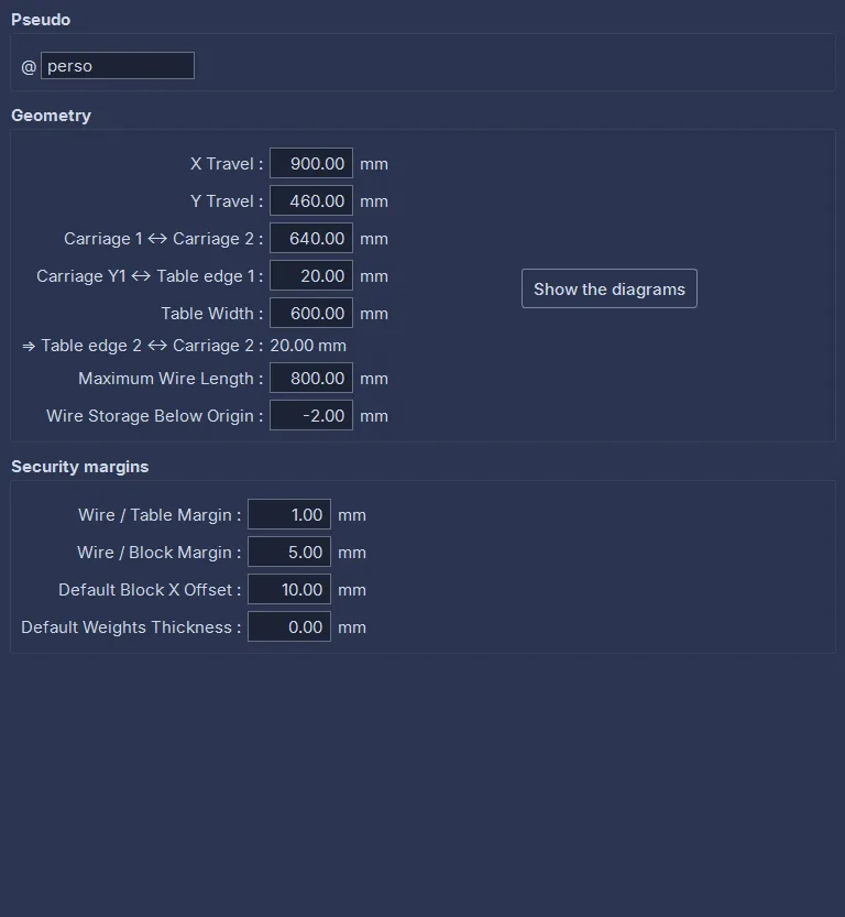
- Pseudo: 1 to 10 characters, unique, no spaces. It identifies the machine in the lists and serves as the context of the materials.
- Geometry: the X Travel (horizontal) and the Y Travel (vertical) of the carriages; Carriage 1 ↔ Carriage 2, the distance between the articulation points of the wire on the two carriages (the point around which the wire pivots on each carriage); Carriage Y1 ↔ Table edge 1, from the articulation point of carriage 1 to the near edge of the table; the Table Width. The remaining distance, ⇒ Table edge 2 ↔ Carriage 2, is computed and displayed: it lets you check the measurements. These measurements must be taken with care, as they determine the accuracy of the cut. The Maximum Wire Length is used to check that a slanted cut does not need more wire than there is. The Wire Storage Below Origin: if the wire is stored between two cuts in a groove of the table (handy for sliding the blocks without catching the wire), enter how many millimeters below the surface of the table it lies, as a negative value; 0 without a groove. To the right of the fields, the Show the diagrams button (see below).
- Security margins: the Wire / Table Margin, below which the wire never goes down; the Wire / Block Margin above the block, for the moves that pass over it; the Default Block X Offset and the Default Weights Thickness, taken up by the Cutting tab for each new document.
Show the diagrams, active in both phases, opens the small Geometry parameters window: two drawings of the machine that show what each field of the Geometry and Security margins frames measures. The dimensions carry the names of the fields, abbreviated where space is short (“Carr.” for carriage). The drawings are legends: they show no values and are not to scale. The window opens in the center of the configuration, surrounded by a light frame; it stays on top without blocking it, can be moved with the mouse, closes with the Esc key and closes together with the configuration.
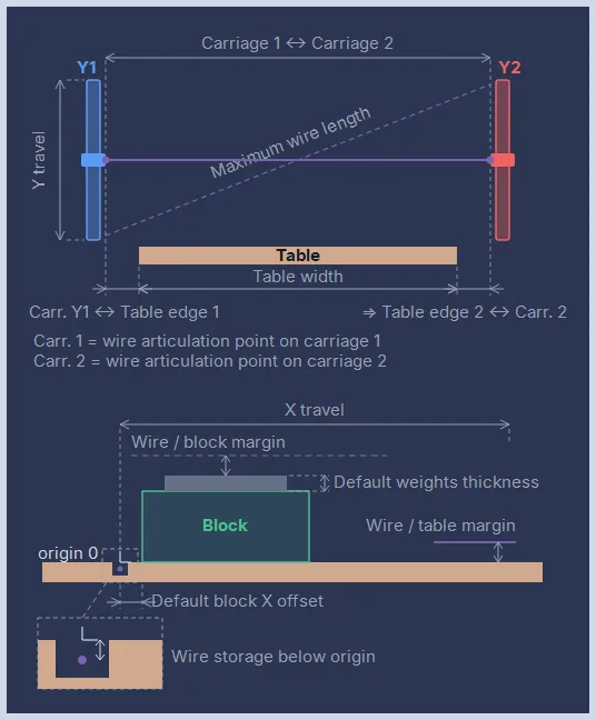
- Front view: the machine seen from the front. The two carriages on their vertical rails, carriage 1 in blue, carriage 2 in red; the wire stretched between their articulation points, which the notes of the drawing call “Carr. 1” and “Carr. 2”; the table. The dimensions: “Carriage 1 ↔ Carriage 2”, “Carr. Y1 ↔ Table edge 1”, “Table width”, ”⇒ Table edge 2 ↔ Carr. 2”, the “Y travel” along the rail of carriage 1, and the “Maximum wire length” on a wire stretched at an angle.
- Side view: the machine seen along the axis of the wire. The block placed at its “Default block X offset”, the weights on top of it (“Default weights thickness”); the passage of the wire above the block (“Wire / block margin”) and a cutting path just above the table (“Wire / table margin”); the “X travel” from the origin, marked by an L-shaped corner. A magnifier, at the bottom left, enlarges the wire storage: the “Wire storage below origin” dimension runs from the surface of the table to the wire stored in its groove.
6.3.2 Interface
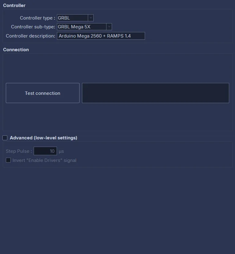
- Controller: the type (GRBL or IPL5X), the GRBL sub-type (GRBL Mega 5X or grblHAL), and a free description of the hardware, as a reminder.
- Connection: Test connection opens the port, reads the firmware and the board, and shows them next to the button, without changing anything.
- Advanced (low-level settings): a box at the top of the frame, unticked by default, which grays out its fields as long as it is not ticked. The Step Pulse, the pulse width of the STEP signal (GRBL only; 10 µs suits every board), and Invert “Enable Drivers” signal, the inversion of the driver enable signal, to tick when the drivers are enabled at the logic level opposite to the one the board gives. The BTT SKR Pico v1.0 and Default IPL5X templates have it ticked, for the common drivers (stepsticks, DRV8825, TMC), which are enabled on a low state.
- IPL5X interpolator (IPL5X, instead of the GRBL settings): the interpolation Frequency (50 kHz unless the drivers require otherwise), the Acceleration slope (1-9) (1 gentle, 9 steep), Vmax without acceleration (the speed at which the motors start without stalling, the most important value in hot-wire cutting) and Vmax with acceleration, the automatic motor power cut-off, Auto Off Motors, and its Auto-off delay, in seconds.
6.3.3 Axes
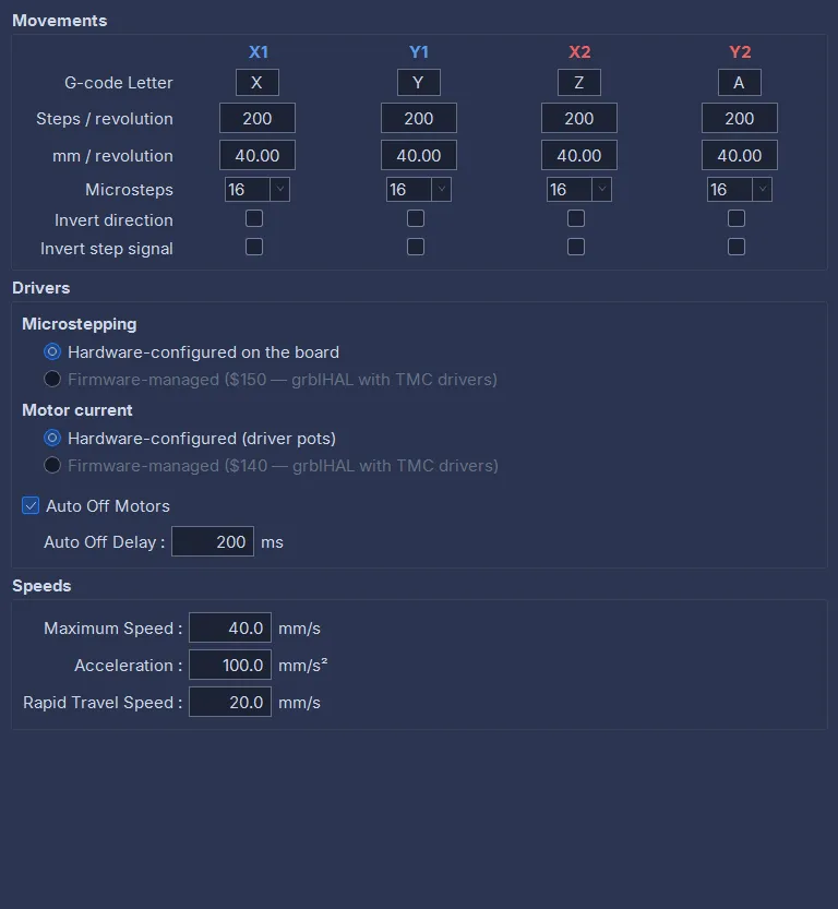
- Movements, one column per axis (X1, Y1, X2, Y2): the G-code Letter of the axis (X, Y, Z, A by default), the Steps / revolution of the motor, the mm / revolution (the travel of the carriage for one turn of the motor), the Microsteps of the driver (a power of 2 from 1 to 256), Invert direction and Invert step signal. A Motor current (mA) row appears when the current is managed by the firmware. A microstep value that is not a power of 2, in an old or hand-edited file, is brought back to the nearest power of 2 on loading.
- Drivers (GRBL): who sets the microsteps and the motor current. Hardware-configured (jumpers, driver potentiometers): the microstep value entered is only used to compute the steps per millimeter. Firmware-managed (grblHAL with TMC drivers over UART): the values are sent to the board; the motor power terminal block must be connected for them to be accepted. Below, Auto Off Motors and its delay, in milliseconds: unticked, the motors stay powered at all times. During a direct cut, HotWire4X keeps the motors powered anyway; in the test panel and the manual movement window, only when the Motors always energized box is ticked.
- Speeds: the Maximum Speed and the Acceleration of the carriages (GRBL), the Rapid Travel Speed used outside the material (approach, return, moves around the block), which can be well below the maximum.
- IPL5X outputs (IPL5X): which of the ten outputs of the interface carries the STEP signal and the DIR signal of each axis.
6.3.4 Safety
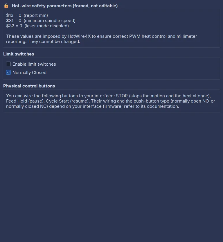
- A banner recalls the three forced GRBL parameters: report in millimeters (
$13), zero minimum heat ($31), laser mode disabled ($32). They cannot be modified; they protect a board that may have served on a CNC mill or a laser engraver. A board that does not report one of them is considered non-compliant (amber dot): Transfer & Test writes them. - Limit switches: Enable limit switches, and tick Normally Closed if the switches are normally closed. The two boxes are independent: the type of the switches can be set before enabling them.
- Physical control buttons: the STOP button, which immediately stops the movement and the heat (chapter 5), the Feed Hold (pause of the movement) and the Cycle Start (resume). Their wiring depends on the firmware. On grblHAL, a table (STOP button, Feed Hold (pause), Cycle Start (resume)) indicates the buttons that are not normally open; ticking a box asks for confirmation, because an input declared normally closed without a wired loop keeps the board in alarm. On GRBL Mega 5X, the type of the buttons is fixed by the firmware: the frame only contains an explanation.
6.3.5 Heating and material
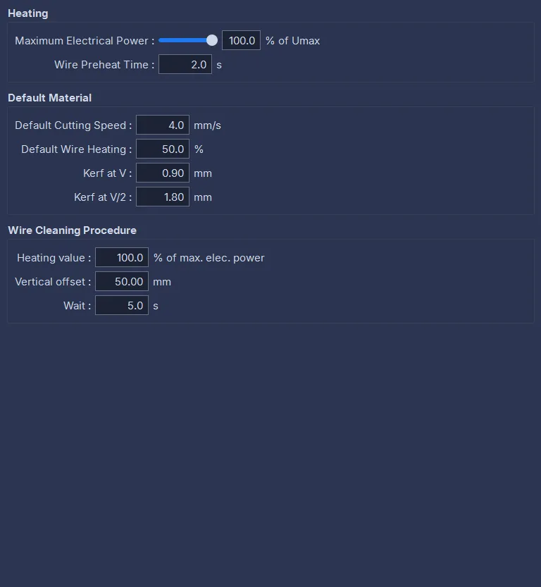
- Heating: the Maximum Electrical Power in %, a cap that protects a short wire (set it so that the maximum just begins to make the wire glow red); the Wire Preheat Time before the first movement of a cut.
- Default Material: speed, heat and kerfs offered to a new machine.
- Wire Cleaning Procedure: the heat (capped by the maximum), the vertical movement and the wait in the high position.
6.3.6 Workflow
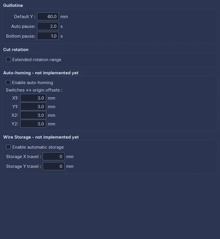
- Guillotine: the Default Y height offered in the Cutting tab, the Auto pause at the top of the cut and the Bottom pause before the wire is switched off.
- Cut rotation: Extended rotation range. Unticked, the block rotation slider of the Cutting tab (chapter 5) stops at “leading edge perpendicular to X”: turning further only widens the footprint on the table. Ticked, the slider goes up to ±75°, for unusual placements or to fit a part at the edge of the table.
- Auto-homing and Wire Storage: reserved, not used for the moment.
6.4 Transferring and testing
6.4.1 GRBL interface
A GRBL board keeps its settings in a list of numbered parameters ($100, $110…). The middle column makes the link.
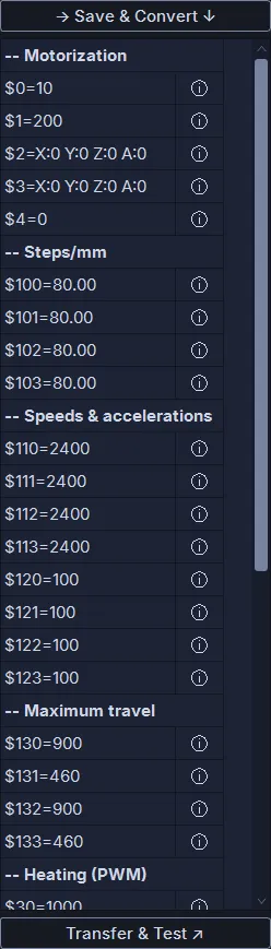
- → Save & Convert ↓ saves the tabs and computes the list of parameters to send, shown by category (a tooltip explains each one).
- Transfer & Test ↗ sends the list to the board, reads it back and compares. The result appears in the log of the test panel; the dot turns green when everything matches. The button is only active after a conversion, and any change to a field disables it until the next conversion: you only transfer what has just been computed and saved. A board whose firmware is not that of the declared sub-type (Interface tab) is refused, and the log explains why.
On a grblHAL board whose drivers are managed by the firmware, the motor power supply must be connected: otherwise the current and microstep parameters are refused, the log says so and a window recalls it.
6.4.2 IPL5X interface
The IPL5X interpolator keeps a table of settings in permanent memory. A single button, Save, Transfer & Test ↗, saves the tabs, writes the table into memory 0 of the interface, reloads it, reads it back and compares. A window gives the result; the dot turns green when the read-back matches, amber otherwise. The name of the table is the pseudo of the machine, truncated to eight characters.
6.5 Test panel
In the Modify / Test phase, the right-hand column drives the machine live, to check the direction of the axes, the speeds and the heat without leaving the configuration. It takes up the controls of the manual movement window of the Cutting tab (chapter 5).
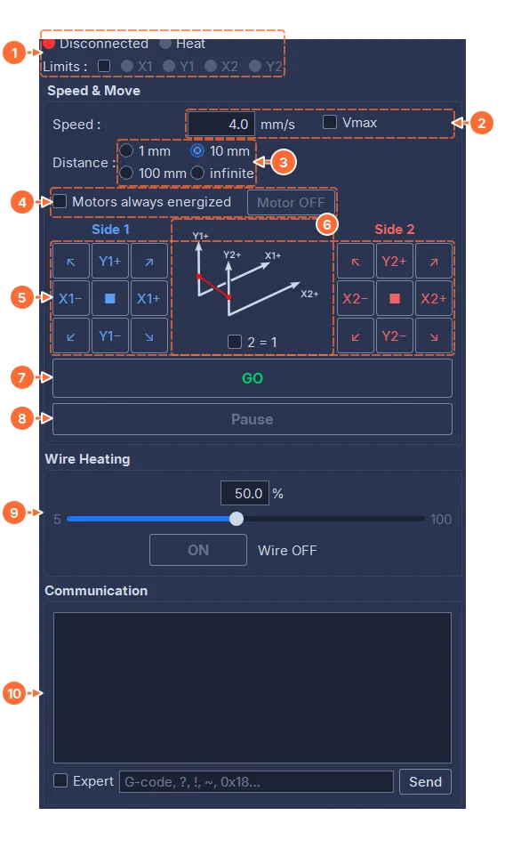
- The indicator lights: State (“Disconnected” without an interface), Heat, then the Limits of each axis; the small box in front of them shows whether the limit switches are enabled (Safety tab). On GRBL, Rearm appears next to Heat when the board is in alarm: it clears the alarm without commanding anything (chapter 5, manual movement). On IPL5X, the axis lights are replaced by the Origin and End loops.
- The Speed of the move, in mm/s; Vmax moves at the maximum speed of the machine (Axes tab). On IPL5X, three choices instead: V (the speed entered), Vmax and Vmax accel. (the two speeds of the Interface tab).
- The Distance: 1, 10 or 100 mm, the length of the path traveled, diagonally as well as in a straight line; infinite turns GO into a button to hold down (see below).
- Motors always energized and Motor OFF. Unticked (the default), the machine’s power-off delay applies: once this delay has elapsed after a move, the motors are released and the carriages can be moved by hand, for example to set the zero. Ticked, the motors stay powered. The machine’s setting is restored on leaving the Modify / Test phase and when the window closes. On a machine set to keep its motors powered at all times (Auto Off Motors unticked), the box is ticked and grayed out: this is changed in the Axes or Interface tab. Motor OFF, next to it, releases the motors right away, even those of a machine powered at all times, to move the carriages by hand; the box and the machine’s setting stay as they are, and the next move powers the motors again. It is only active at rest: interface connected, no move in progress and, on GRBL, heat off.
- The Side 1 (blue) and Side 2 (red) pads: eight directions around a central button that clears the chosen direction. The four axes carry the names of the axes diagram (X1+, X1−, Y1+, Y1− on side 1, X2+ … Y2− on side 2), the four diagonals an arrow. Only one direction per side; a side without a direction does not move.
- Between the two pads, the axis-direction diagram of the Manual movement window, and below it 2 = 1: side 2 takes the direction of side 1, then the two pads stay identical.
- GO starts the move; the two sides leave and arrive together. During the move, the button becomes STOP.
- Pause suspends the move, Resume continues it (GRBL only).
- Wire Heating: the value in %, the slider from 5 to 100 %, ON / OFF and the state of the wire (“Wire OFF”, “Heating active”).
- Communication: the log of the exchanges with the interface; the Expert box enables the command line and Send (GRBL only).
A move is refused as long as an enabled limit switch is triggered: clear it, or disable the limit switches in the Safety tab. The STOP button wired to the board stops the move and cuts the heat; HotWire4X gives control back at once, without a window, and the board accepts the next command.
Continuous move. With the infinite distance, GO is held down: the carriages move as long as it is pressed and stop as soon as it is released, even if the pointer has left the button. The wire stays hot between two presses.
Heat on GRBL. The heat is switched on before a move, never during it: ON / OFF is grayed out during any move, pauses included. Once the heat is on, the slider gives way to four buttons, −5, −0.5, +0.5 and +5, which adjust it live, even during a move. It stays on from one move to the next until OFF. STOP briefly cuts the heat, which comes back on by itself at the same value.
Heat confirmation (GRBL). HotWire4X sets the heat live through a correction of the board (an “override”), which the board only confirms in its status report. As soon as ON is pressed, the move settings, the pads and GO stay grayed out until the board reads the requested heat. Without confirmation after 5 s, the “Heat not confirmed” window gives the heat read and the heat requested, and invites you to check the $30 / $31 settings of the board and that its firmware accepts overrides; if the board no longer sends a report, it shows “The board no longer responds: check the USB cable and electrical interference.” Retry sends the setpoint again and restarts the delay; Turn the heat off, the default choice, switches the wire off. Once the heat is confirmed, a heat read away from its setpoint for 3 s turns the Heat light red, followed by ⚠; it goes back to normal as soon as the board reads the setpoint again.
Heat on IPL5X. The slider stays active at all times, and so does ON / OFF, moves included. ON is refused, with a message, when the PWM switch of the interface is on OFF: the wire could not heat. The status line then shows “PWM switch OFF”, or “PC/MANU on MANU” when the PC/MANU switch of the interface is on MANU.
Expert mode. The command line sends a raw command to the board, a $N=value parameter for example. When the window closes, the parameters changed this way are compared with the configuration and the differences are listed in the “Expert mode summary” window. Nothing is corrected automatically: to align the board and the configuration, modify the fields and convert, or send the configuration again with Transfer & Test.
On leaving the Modify / Test phase, or on closing the window, the move in progress is stopped, the heat is cut and the machine’s motor power-off delay is restored.
6.6 Finding the interface, the status dot, releasing the port
Find interface looks for the interface on the USB ports, reads its firmware, then compares its parameters with the active machine. The dot sums up the result:
- green: interface recognized, parameters compliant, cutting is possible;
- amber: interface recognized but some parameters differ, or a requested option is not available on the board; Transfer & Test solves the usual case;
- red: no interface, or a firmware of a different family from the machine.
The tooltip of the dot gives the details. When the microsteps or the motor current are declared as managed by the firmware but the board does not expose them, the Axes tab also shows a ”⚠ Configuration mismatch” banner: Switch to Hardware-configured corrects the machine, Keep configuration hides the banner and the dot stays amber.
An interface recognized at startup (startup screen) is taken over by the main window; after a period of inactivity the port is closed, and it reopens by itself at the next cut. The test panel and the manual movement window count as activity, on GRBL as on IPL5X: the port stays open as long as they are displayed.
An unplugged USB cable turns the dot red in less than a second; its tooltip says “Controller disconnected on …” and invites you to plug the interface back in, then click Find interface. On IPL5X, when the test panel or the manual movement window is open, the link reopens by itself when the cable is plugged back in, and the dot returns to the state it had before.
Release the port (configuration window, browse phase) closes the port without closing HotWire4X: another program can then open the board, for example to read back its parameters. The dot turns red until a new Find interface, because the other program may have modified the board.
6.7 Flashing a firmware
The Machine menu offers two firmware update utilities, with no third-party software. In both windows, the firmware file is chosen at each opening: it is not remembered.
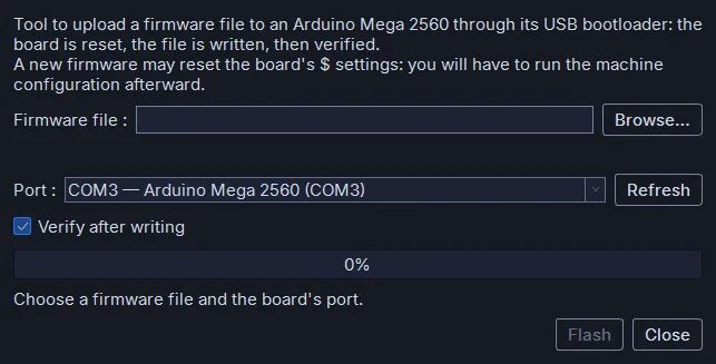
Flash the Mega 2560…: choose the .hex file of the firmware and the port of the board (Refresh reads the list of ports again), tick Verify after writing, Flash then confirm. The board is reset, the file written then read back. A new firmware may reset the parameters of the board: afterward, run Find interface again, then Transfer & Test.
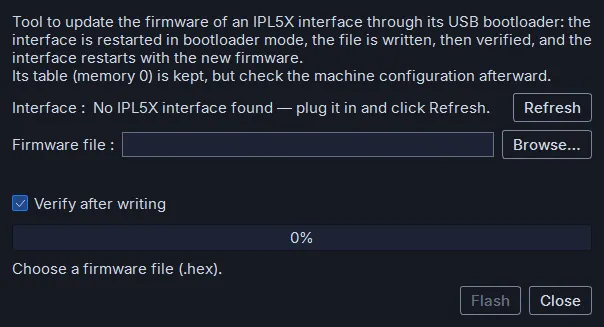
Flash the IPL5X…: the Interface line shows the interface found and the version of its firmware (Refresh starts the search again). Choose the .hex file, Flash then confirm: the interface is restarted in bootloader mode, the file written and verified, then the interface restarts. The settings table is kept when the file only contains the program; the line under the file shows whether the file contains a table, which would replace the one in memory 0. A canceled update leaves the interface in bootloader mode: run the update again.
In both cases, the port is released before the operation and the dot turns red afterward.
6.8 Wiring and firmwares
The wiring of the supported boards, the HotWire4X firmwares and their installation are described on the website, on the technical prerequisites page: Arduino Mega 2560 + RAMPS 1.4, BTT SKR Pico v1.0, IPL5X.