5.1 Overview
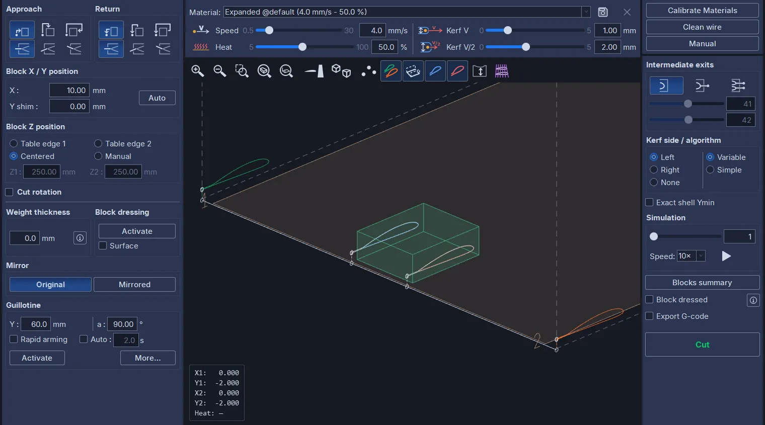
The Cutting tab turns the project from the Design tab into machine movements. As soon as you enter it, the cut is computed with the current material and settings, and the 3D view shows what the wire will do: the paths on the two faces of the block, the carriage paths, the table, the block.
Every change to a setting recomputes everything at once. The view therefore always shows exactly what will be cut, based on what the software knows: the project, the machine, the material, the block position. If the result on screen or on the table does not match what you expect, the cause lies in one of these pieces of information.
The cut is made on the active document: the pressed chip at the top right, drawn as a tab open onto the page (chapter 3). It can be a project from the Design tab, a panel transferred from the Wing tab, a Sections sheet, a view. Clicking another chip shows the cut of that document without leaving the tab. Each document keeps its own cutting settings (approach, block position and rotation, kerf, weights…), saved with the workspace.
When nothing can be computed, a message at the top left of the view gives the reason: no project loaded, no machine configured, a side with fewer than two points, a different number of points on the two sides, or “Project spacing exceeds the table width.”. This last message also covers a rotated block whose footprint no longer fits on the table (see the cut rotation).
The tab’s status bar shows, in the center, the number of the current simulation point and the speeds of the four axes on the segment that starts there, followed, where relevant, by the face speed ratio (see the rotation) and the number of overshoots (see the checks). On the left are Show G-code (GRBL interface, see the G-code export) and the red License off indicator, shown as long as no license is active (chapter 16).
5.2 The material banner

- Material: the list of materials in the library (chapter 7), each with its speed and its heat. Choosing a material loads its four values into the sliders.
- The floppy-disk button opens the material editor (save the slider values in a new or existing material, rename); the × button deletes the selected material after confirmation (it is grayed out on a system material).
- Speed in mm/s: the speed of the wire in the material. On a tapered cut, the faster side runs at this speed and the other one more slowly.
- Heat in % of the maximum power, never below 5 %. The heat combined with the speed determines the width of the kerf.
- Kerf V and Kerf V/2 in mm: the width of the groove melted at the cutting speed and at half that speed. They come from the calibration of the material (chapter 7) and are used for the wire offset.
- Calibrate Materials opens the advanced guillotine with the calibration procedure (chapter 7); Clean wire starts the wire cleaning cycle; Manual opens the Manual movement window (see the end of the chapter).
The sliders are settings of the day: changing them writes nothing into the material. This is intentional: you often adjust the heat by a few percent depending on the temperature of the workshop, or try a slightly different speed. When the right value is found, the floppy-disk button saves it into the material. The document remembers the name of the chosen material, not the slider values. If this material is missing from the library when the file is opened, the “Material not found” window says so (chapter 7).
5.3 The 3D view
5.3.1 The elements
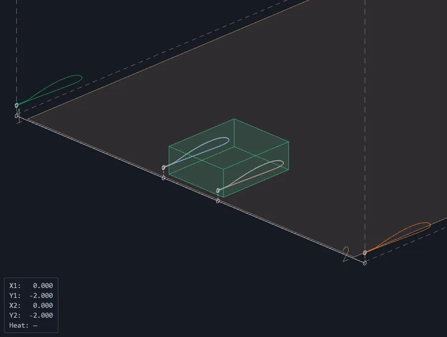
- The table of the machine, with its edges numbered 1 and 2, and in dotted lines the useful area of each carriage.
- The carriage paths, in green for carriage 1 and in orange for carriage 2: these are what the machine executes. A dotted segment is traveled at rapid speed: 3 mm dashes separated by 2 mm, anchored to the table, so that the way out and the way back on the same line (the climb out of the groove and the descent back into it) overlap exactly, and a rapid move of a few millimeters stays visible. A thick segment (yellow in the dark theme, dark orange in the light theme) asks the carriage for a speed above the machine’s maximum. A red segment between the two carriages signals a wire longer than the maximum allowed.
- The cutting paths on the two faces of the block, in white, with the project profile drawn over them in blue (side 1) and in red (side 2), to compare the offset path with the drawing.
- The block, translucent (rotated when the cut rotation is active), and the four white rings of the origin, where the wire is stored before and after the cut.
- The stop points, as pink rings, on the four planes.
- The speed changes of the approach and the return, as white rings on the four planes, always shown: the end of the rapid traverse, a few millimeters before the block, and where it resumes on the return; when Block dressed is unticked, the top of the rapid climb out of the groove.
- The wire, at the simulation position, from one carriage to the other through the two faces of the block.
- At the bottom left, the HUD, a box of values overlaid on the view: the X1, Y1, X2, Y2 coordinates of the carriages, the heat and, for a guillotine, the speed. With the wire at rest in its storage position, the heat shows a dash; during the simulation, the HUD shows the setpoints; during a cut, the values read from the interface.
- At the top right, a banner recalls a particular mode: MIRROR ACTIVE, BLOCK DRESSING, GUILLOTINE, ADVANCED GUILLOTINE or WIRE CLEANING. At the top center, the SIMULATION banner is shown while the simulation is animated.
5.3.2 The toolbar

- Zoom +, zoom −, zoom to selection (Z key), View project (frames the carriage paths and the block) and View all (the whole table).
- Side view / top view, then orthographic / perspective 3D. In side view, the dotted rectangles mark the travel limits of the machine: the carriage paths must stay inside them.
- Five displays: the trajectory points on the four planes (hidden at first), the carriage trajectories, the table and the useful area, the cut on side 1, the cut on side 2.
- Dimensions (hidden at first): the waste-shell heights and the position of the block on the table (see below).
- Wire generatrices (hidden at first). A generatrix is the straight line of the wire at a given moment, between a point on side 1 and the paired point on side 2. The display draws the one of each pair of points: in gray for the approach and the return, in violet for the cut; a wire that is too long stays red. When the cut rotation is active, it adds the two trailing-edge lines and the trace of the wire on the entry face of the block (see the rotation). The button presses itself when you activate the rotation.
The mouse works as in the Design tab: mouse wheel to zoom, right button to pan, middle button or Alt + left button to rotate.
5.3.3 The dimensions
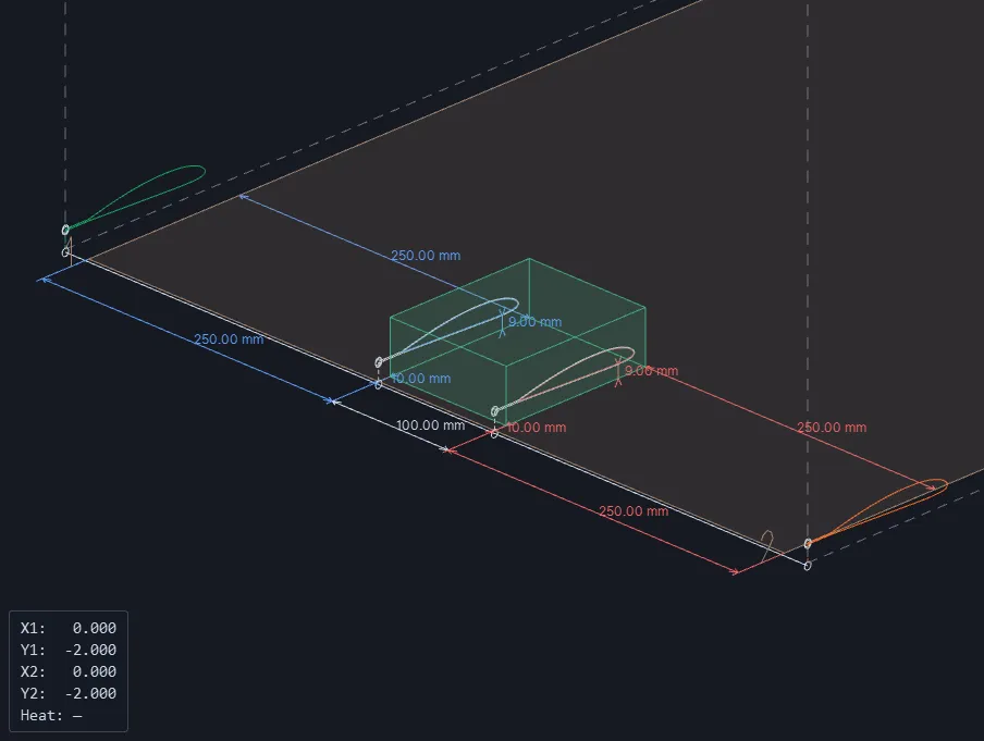
The Dimensions button shows two families of dimensions.
The waste-shell heights. The waste shell is the offcut that surrounds the part after the cut; the lower one follows the shape of the part and serves as a cradle for gluing or sheeting it. For each face, the dimension gives the height between the underside of the block and the surface of this shell: the lowest point of the cut, minus the half-kerf that this face burns at that spot. Each face counts its own kerf: on a tapered cut, the slower face melts wider and its dimension is smaller. This is the value to note in order to join two pieces of a wing cut in several passes (chapter 4, intermediate profile); the Exact shell Ymin option (see the wire offset) brings it back to the height of the project.
The block position on the table. The dimensions are drawn in the plane of the table, in blue for side 1 and in red for side 2. Each end face has an entry corner: its corner on the origin side, the one the wire reaches first.
- In Z, a chain of three dimensions crosses the table: from edge 1 to the entry corner of face 1, from that corner to the one of face 2 (in white), then from that corner to edge 2. The three dimensions add up to the width of the table. The chain passes in front of the wire origin, in the empty area, and extension lines connect it to the edges of the table and to the two corners.
- In X, for each face, the distance between the wire origin and its entry corner, on the table.
- In Z again, for each face, the gap between its edge of the table and its exit corner (the X+ corner, at the other end of the block), drawn on the table at that corner. A block rotated on the table is thus set by its four corners; a block that is not rotated repeats the dimensions of its entry corners.
These seven dimensions are the measurements to transfer to the table to place the block by hand. A negative value signals a block that overhangs the table. A block placed on a shim is connected to the table by a vertical line at each of its four corners. When the block is rotated, the two corners of a face no longer have the same Z and the dimensions are no longer equal to Z1 and Z2. View project also frames the dimensions shown.
5.4 Approach and return
The wire starts from the origin (the storage position under the table), reaches the first point of the cut, travels through the project, then returns to the origin. The Approach and Return frames set these two paths.
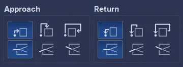
First row, the face through which the wire enters or leaves:
- From left: the wire rises to the height of the first point, then crosses the left margin of the block.
- From top: the wire rises above the block (thickness + shim + the machine’s wire / block margin + weights), moves above the first point and comes down. The climb and the traverse above the block are made at rapid speed, on the way in as on the way out. If this clearance height exceeds the machine’s Y travel, it is brought back to the travel and the traverse is made at cutting speed.
- From right: the wire passes above the block, comes back down on the right and enters through the right face.
Second row, for an entry or an exit from the left, the way to cross the margin:
- Horizontal;
- Parallel to first segment: the approach arrives in line with the first segment of the cut;
- Parallel to last segment: in line with the last one.
The two parallel options require, on both sides, a left margin (Xmin side) of more than 0.1 mm and a reference segment that rises, with a slope of 70° at most. When the geometry does not allow it, their buttons are grayed out, and a choice that has become impossible reverts to Horizontal. Combining an approach parallel to the first segment and a return parallel to the last one makes the entry and the exit cross at the trailing edge of a wing, which gives a clean trailing edge.
A symmetric fuselage section, for example, is cut starting from the top: approach and return From top.
The approach paths take into account the machine’s wire / block margin, the thickness of the weights (see below) and the Block dressed box (right column).
5.5 Intermediate exits
The Intermediate exits frame adds up to two exits from the block to the right during the cut: the wire leaves horizontally to 10 mm to the right of the block, stops (a stop point), then comes back to the same point and continues.
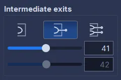
Choose None, 1 exit or 2 exits, then place each exit with its slider or its point number. The sliders are readjusted to the number of points of the project each time you enter the tab; on the first entry they are placed at the rightmost point (the leading edge) and at the next point.
This is used to split the waste into two or three pieces, or to wipe the wire halfway through. A small mark remains on the part where the wire leaves and comes back in.
5.6 Block position
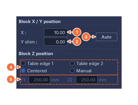
- X: the horizontal distance between the origin and the point of the block closest to the origin.
- Y shim: the height of the shim under the block. Zero when the block rests directly on the table.
- Auto resets X to the machine’s default value (10 mm at first) and the shim to 0, then increases one or the other just enough for the carriage paths to stay within the machine’s travel. These are minimum values: then round X up to a value that is easy to measure on the table, and match the shim to a board you have on hand.
- Z, the position between the two edges of the table: Table edge 1 and Table edge 2 push the block against an edge; Centered puts it in the middle; Manual lets you enter Z1 or Z2.
- Z1 (from edge 1 to the side 1 face) and Z2 (from the side 2 face to edge 2): the other value follows, since Z1 + spacing + Z2 = table width. The fields always show the effective position, even outside Manual mode.
When the cut rotation is active, Z1 and Z2 refer to the footprint of the rotated block, that is, the width it actually occupies on the table: Z1 + footprint + Z2 = table width, and Centered truly centers the rotated block. The dimensions of the 3D view (see above) give the measurements to transfer to the table.
The position affects the movements of the carriages and the accuracy: choose the one that minimizes the movements. The position to favor is alignment with the edge of the table on the side of the larger cut (see the speed check).
5.7 Cut rotation
The Cut rotation frame, under the block position, brings together two settings meant for panels with a strong sweep or a strong taper: the rotation of the block on the table and the synchronization law λ (lambda). The box in front of the title activates the tool. Unticked, the frame shrinks to its title and the cut stays the classic cut.
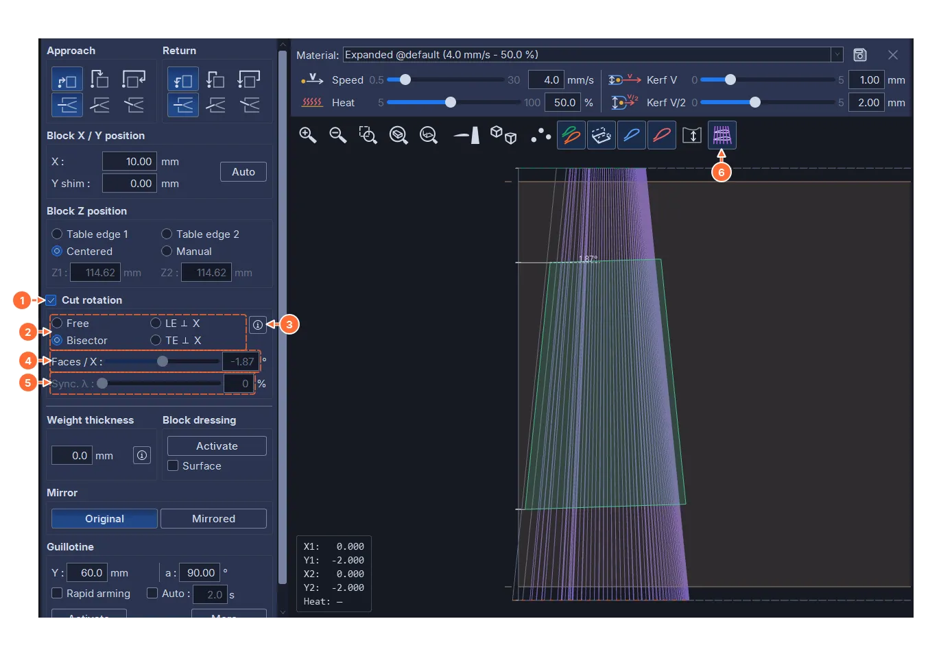
- The Cut rotation box activates the tool and unfolds the frame.
- The mode: Free, LE ⊥ X, Bisector, TE ⊥ X.
- The ⓘ button opens the “Block rotation & synchronization” help page, which stays open while you adjust the settings.
- Faces / X: the rotation angle, with the slider or the field, in degrees.
- Sync. λ: the synchronization law, from 0 to 100 %.
- Wire generatrices, pressed automatically when the tool is activated.
The mode, the angle and λ are saved with the document. The frame is grayed out as long as the mirror or a guillotine is active; it stays adjustable during dressing.
5.7.1 Rotating the block on the table
Cut the classic way, a panel with a strong sweep makes one carriage travel much further in X than the other, and lengthens the wire. Rotating the block around the vertical trades this X travel and this wire length for table width: the block takes up more of the width of the table (Z) and less of its length (X), and the wire works shorter. The cut part is exactly the same whatever the angle; only the carriage paths and the wire length change.
The Faces / X angle is the angle between the end faces of the block (side 1 and side 2) and the X axis of the table: it is the only angle that can be measured directly on the machine. 0° is the classic cut, faces parallel to X. A positive angle rotates the block so that a face, followed from its trailing edge (TE) to its leading edge (LE), gets closer to edge 2 of the table: this is the direction of a swept-back wing.
The four modes:
- Free: the angle is set by hand.
- LE ⊥ X: the leading edge perpendicular to the X axis.
- Bisector: the angle halfway between the LE line and the TE line. The leading edge and the trailing edge are then inclined by the same angle, in opposite directions, relative to the perpendicular to X: this is the setting where the more inclined of the two is inclined the least.
- TE ⊥ X: the trailing edge perpendicular to the X axis.
In the last three modes, the angle is derived from the planform (chords, sweep, spacing): it is displayed but cannot be edited, and it follows the project when its chords or its sweep change. The value of the Free mode is kept separately: going back to Free restores it.
The slider covers the useful range: by default, it stops at “leading edge perpendicular to X” (the angle of the LE ⊥ X mode); beyond that, the footprint grows without shortening the wire. When ticked, the Extended rotation range box, in the Workflow tab of the machine configuration (chapter 6), opens the slider to ±75°, for an unusual placement or a block set against an edge of the table. On a project without sweep, the range is zero and the angle cannot be set.
The footprint of the rotated block must fit within the width of the table; otherwise the view shows “Project spacing exceeds the table width.”. A panel that the Wing tab judged narrow enough for the table, without rotation, may no longer fit once rotated.
In top view, or in a 3D view that looks clearly downward, a dimension recalls the angle: a dotted reference line parallel to X from the entry corner of the side 1 face, an arc and the value.
The rotation also acts on the rest of the tab:
- the wire leaves its storage position vertically, as without rotation; all the other points of the approach, the cut and the return rotate with the block;
- Mirrored reverses the effective angle by itself: set the angle in Original;
- dressing rotates with the block, whose dressed faces stay square;
- the guillotines ignore the rotation;
- the block position dimensions follow its rotated corners: these are the ones you transfer to the table (see “The dimensions”);
- the G-code carries a comment line that gives the angle (see the export).
5.7.2 The synchronization law λ
In a four-axis cut, point n of side 1 and point n of side 2 are reached at the same moment: they are paired points (the synchronization of the Design tab, chapter 4). When the two chords differ, the wire travels along the small chord more slowly than along the large one; with the same heat, the slow face melts more. On a strongly tapered panel, the speed of the small-chord face can fall outside the calibrated range between V and V/2 (chapter 7).
Sync. λ redistributes these points to bring the speeds of the two faces closer:
- 0 %: the project’s pairing is kept; this is the starting value;
- in between: the difference in speed, and therefore in heat, decreases proportionally;
- 100 %: the same speed on both faces.
The two end profiles stay exact; the intermediate sections are deformed, all the more as λ is large (less than 1 % of the local chord at 100 % on a panel whose chords are in a 3 to 1 ratio). Raise λ just enough for the small-chord face to stop burning. To guide this setting, the status bar shows the face speed ratio (“Face speed ratio: …”): the average speed of the slow face divided by that of the fast face. It appears as soon as the tool is active on a simple wing profile and the ratio departs from 1, even at λ = 0, and gets closer to 1 as λ increases.
Splitting the panel into two shorter panels gives the same balance with no deformation at all, since each one has a lower chord ratio: splitting into pieces at the transfer from the Wing tab (chapter 8) or intermediate profile (chapter 4).
λ only applies to a simple wing profile, made of two arcs (upper surface and lower surface) joined at the leading edge, with no junction path. A hollow, a spar detour or an X-cut at the leading edge grays out the Sync. λ row, and the project’s pairing is used. λ is also ignored during dressing.
On a tapered panel, with λ greater than 0, the end of the wire on the small-chord side goes past its trailing edge, into empty space, while the other end is still cutting. HotWire4X runs each of these wires through the trailing-edge line, the segment that joins the trailing edges of the two profiles, which keeps the trailing edge sharp at every section. In return, this end dips during the upper-surface pass and rises during the lower-surface pass, sometimes by several tens of millimeters. If the wire then goes below the table, the travel check refuses the cut: raise the block with Auto (a shim) or reduce λ.
The Wire generatrices display shows the effect of λ. With the tool active, it also draws the two trailing-edge lines and the trace of the wire on the entry face of the block: the intersection of each generatrix with this face, as connected rings, and during the simulation that of the current wire.
5.8 Weights and mirror
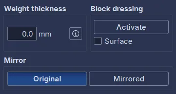
Weight thickness. It is strongly recommended to place weights on the block to hold it still and keep the waste from deforming during the cut. Their height is added to the machine’s wire / block margin for all the movements above the block: approach and return from the top or from the right, dressing. Enter the exact thickness, the safety margin is already counted. Do not place a weight in line with an entry or an exit from the top. The starting value is the machine’s default weights thickness (chapter 6); the ⓘ button recalls its role.
Mirror. Original cuts the project as it is; Mirrored swaps the two sides and their margins, which cuts the symmetric part: the left wing after the right wing, from the same project. The mirror is not saved in the project. While it is active, the cutting settings are locked, except the mirror itself, dressing, the guillotine, the simulation and the blocks summary; the 3D view shows MIRROR ACTIVE. A rotated block is rotated the other way, by itself.
5.9 Wire offset and dressed block
The wire melts a kerf of a certain width; for the part to have the dimensions of the drawing, the wire must pass half a kerf away from the path. The Kerf side / algorithm frame sets this offset.
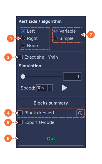
- Side: Left, the most common case, places the wire to the left of the path as it moves forward; Right, to the right; None lays the wire on the path.
- Algorithm: Variable takes into account the speed of each segment (the kerf is wider when the wire moves more slowly) and blends different offsets together; this is the choice to make. It creates two trajectory points per project point, which is normal. It handles back-and-forth paths (a slot, a spar). Simple applies a uniform value per side; it is a fallback solution. On a classic tapered wing (same profile at both ends, no spar), both give the same offset.
- Exact shell Ymin: raises the cut on each side just enough for the surface of the lower shell to fall exactly on the project geometry, whatever the kerf and the speed of each face. The shells of the different panels of a wing then join with no step, and the cores can rest in them to be glued and sheeted. The blue and red profiles drawn on the faces of the block follow the lift. With the kerf on Right, the shell is already exact: the box is ticked and grayed out.
- Block dressed: tick it when the faces of the block are clean and exactly where the cut expects them, for example after a dressing. Ticked, the wire goes toward the block at rapid speed up to 5 mm from its face, then enters the material at cutting speed, and it leaves the block the same way; with an entry from the right, the descent along the right face is also made at rapid speed. Unticked, the whole path toward the block is made at cutting speed, on the way in as on the way out, in case the block sticks out; only the climb out of the storage groove stays at rapid speed. An approach from the top passes over the block at rapid speed in both cases. The ⓘ button, at the end of the row, recalls these rules. The box is grayed out during dressing. The speed-change rings, in the 3D view, show where the wire switches from rapid speed to cutting speed.
- Export G-code: see the G-code export.
- Cut: see starting a cut.
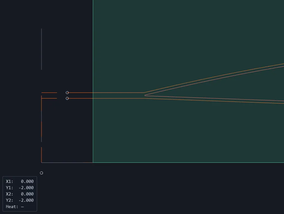
The junction segments defined in the Design tab are never offset.
5.10 Checks and warnings
Before a cut or an export, the cut is checked. A fault blocks the launch, and the “Cut not physically possible” window lists the problems:
- the speeds: a carriage cannot exceed the maximum speed of the machine. The segments concerned are drawn thick, and the status bar counts the overshoots. The typical case is a block pushed against the edge of the table on the side of the small cut: the large side forces too high a speed on the nearby carriage. Move the block closer to the side of the large cut, or find an intermediate position that balances the two sides;
- the travel: the carriage paths must stay within the useful area (the dotted lines of the side view), or in the wire storage position under the origin. Auto finds the minimum position; add some X or a shim;
- the wire length: when the sweep or the dihedral lengthen the wire beyond the machine’s maximum, the segment is red, and the status bar counts the pairs concerned;
- on an IPL5X interface, the speed without acceleration: a cutting segment cannot exceed the maximum speed of the machine without an acceleration ramp.
Two warnings may appear at the top left of the view:
- in red, kerf offset skipped: the profile contains coincident points, the offset computation was abandoned and the wire follows the drawing exactly. Clean up the profile in the Design tab;
- in orange, null segments: two successive points that almost coincide, which can distort the offset; the message gives their number and refers to the Design tab, Cleanup ▸ Successive coincident points ▸ Remove them (chapter 4).
5.11 Simulation
The Simulation frame runs the wire through the cut, without generating any G-code.
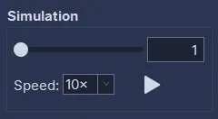
- The slider moves the wire point by point; the field next to it gives the number of the current point (click in it, then step with ↑ and ↓).
- The play button (tooltip “Play / Stop”) animates the wire continuously at the real speed multiplied by the Speed factor (0.5× to 10×, 10× at first). When it reaches the end, playback goes back to the first point.
- Playback stops on each stop point, like the machine waiting for the operator: the stop points set in Design, the intermediate exits, the top of a guillotine without Auto, the pauses of the advanced guillotine (the pink rings). The button goes back to rest, the slider and the field show the stop point; only the play button resumes, from that point. The first and the last points do not stop playback, and the slider ignores the stop points.
- The status bar shows the current point and the speeds of the four axes; during the animation, the 3D view shows SIMULATION and the HUD the heat setpoints (and the speed setpoints for a guillotine). Leaving the tab stops the animation.
The slider works even when the cut is not possible, to examine point by point where it goes outside the limits. Playback, on the other hand, applies the same checks as the launch; it does not require a license.
5.12 Blocks summary
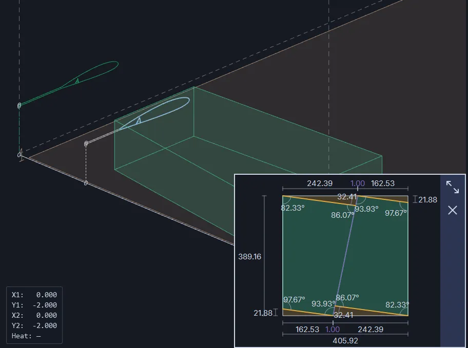
Blocks summary opens a window that shows how to get the raw block out of a sheet of material: seen from above, the base rectangle to cut out, the block placed inside it, the offcuts to remove and all the dimensions to mark them out. The window is floating and non-modal: it opens over the right half of the main window, stays open while you work and during a cut, and follows the active document. Close closes it.
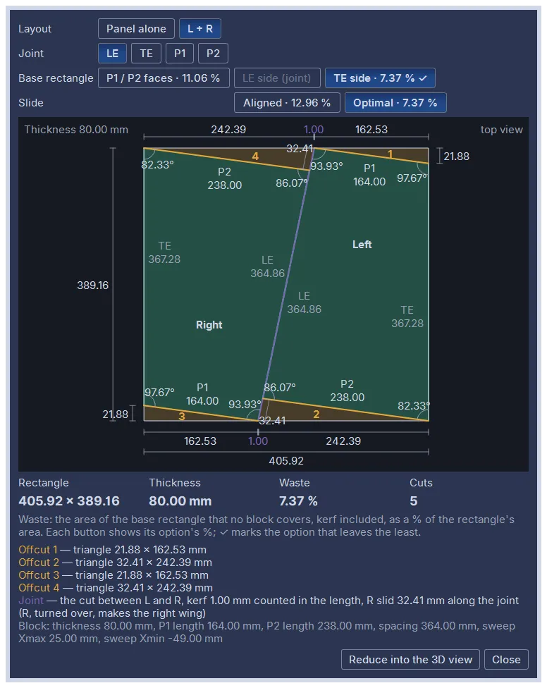
The documents. At the top, the window offers the blocks of all the documents of the workspace: first the free documents (Documents row), then one row per element of the wing, the sections and the views. The active document is pressed; another document chosen here stays displayed until the active document next changes.
The options. Each option shows the percentage of waste it leaves; ✓ marks the one that leaves the least.
- Layout: Panel alone, the block alone, or L + R, a pair: the block and the one of the other wing, rotated by 180° (never flipped into a mirror image), cut from the same rectangle. In mirror mode, the two blocks are swapped and the title of the window ends with “(Mirrored)”.
- Joint (for a pair): the edge or the face that the two blocks share, LE, TE, P1 or P2. On a narrow wing panel, a joint on P1 or P2 puts the two blocks end to end and often leaves less waste. The row is grayed out in Panel alone and keeps its choice.
- Base rectangle: aligned on the faces (P1 / P2 faces) or on an edge of the block (LE side, TE side). The joint edge is never offered: its button is grayed out and marked “(joint)”.
- Slide: Aligned or Optimal. The second block slides along the joint to the position that gives the smallest rectangle; since the wire cuts the joint from one end of the rectangle to the other, the two blocks do not need to share its whole length. Sliding applies to a joint on P1 or P2 with all the rectangles, and to a joint on an edge when the rectangle is aligned on an edge; otherwise the row is grayed out.
On opening, the window shows the block alone on its faces, with the optimal slide; as long as it stays open, it keeps the choices.
The drawing. The rectangle and the blocks are at the same scale on both axes, with the long side horizontal. It shows:
- on each block, “P1” and “P2” with the finished length of the face below them, “LE” and “TE” with the length of the edge seen from above (on both edges of both blocks of a pair, joint included), and in a pair “Left” and “Right”;
- the four corner angles of each block;
- the offcuts, in orange and numbered;
- the dimensions: the dimensions of the rectangle at the bottom and on the left, the chain of each offcut along the sides, and the side of an offcut lying on a slanted joint, dimensioned along the joint.
In a pair, the joint is cut first: each block keeps its offcuts in the corners of its half of the rectangle. The kerf of the joint counts as 1 mm, added to the total length: its dimension “1.00” appears in the chain of each of the two sides that the joint crosses. How to cut each offcut is left to the user: most often a vertical guillotine, with the block lying flat, if it fits on the table; the corner angles give what is needed to set up a slanted cut.
The mouse wheel zooms around the cursor, a drag pans the drawing and a double-click reframes it.
Under the drawing, the window gives the Rectangle (length × width), the Thickness, the percentage of Waste (the area of the rectangle that no block occupies, kerf included) and the number of straight Cuts to make (one per offcut side along a block, plus the joint). A list then describes each offcut, the joint cut and the dimensions of the block: thickness, length of each face, spacing and sweep of each edge.
The thumbnail. On a laptop screen, the window can hide the settings you need to cut out the material. Reduce into the 3D view replaces it with a thumbnail, in the bottom right corner of the 3D view, over a quarter of its area: the cutting plan and its dimensions only, with the same zoom. Its two icons Expand and Close reopen the window with the same choices or close the summary; the Blocks summary button also reopens the window.
5.13 Block dressing and surfacing
A block placed on the table must already have the right width (the spacing of the project). The Block dressing frame brings the other faces to size from the settings of the project: Activate replaces the project path with a dressing path that runs down the left face then the right face of the block, at the margin dimensions.
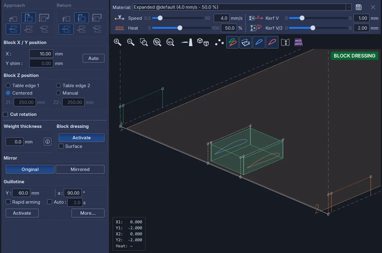
With the Surface box, the top of the block is also brought to height during the outward traverse; without it, the traverse is made at clearance height, at rapid speed. During dressing, the approach and the return are forced from the top, the shim to zero and the intermediate exits disabled; these settings come back when you deactivate it. The block position in X and Z, the rotation, the weights, the mirror and the kerf stay adjustable; a rotated block is dressed in its rotated position.
Dressing is started like a cut. On a tapered block, surfacing takes into account the different kerf of each side: the side that moves more slowly melts wider, according to the same law as the cut (the V and V/2 kerfs of the material).
5.14 Guillotine
The guillotine cuts a sheet in one straight pass: the wire rises to height Y, stops, then comes back down while cutting. It is used to cut sheets to the right width. The project is set aside and comes back when you deactivate the guillotine.
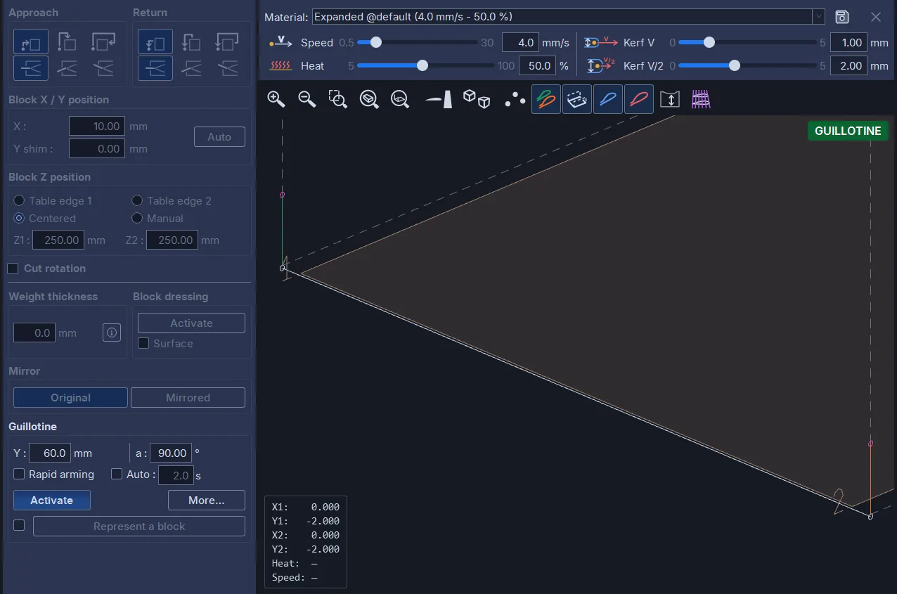
- Y: the height of the cut (at first the machine’s default value). Allow a few millimeters more than the thickness of the sheet, to pass it under the wire.
- a: the angle of the cut relative to the table, 90° for a vertical cut, down to 0.1°; the cut then advances in X by Y × tan(90° − a).
- Rapid arming: the climb is made at rapid speed (otherwise it cuts, at the material speed).
- Auto: at the top, the wire waits for the number of seconds shown, then comes back down on its own; otherwise it waits for you to click Resume.
- Activate shows the path instead of the project; More… opens the advanced guillotine.
- Represent a block: under Activate, while the guillotine is activated, a checkbox and the Represent a block button draw a rectangular block on the table, to see where the cut passes. The button unfolds four fields: X dimension, Z dimension, Y dimension (the height) and X position, the distance from the wire origin to the left face of the block (negative, the block straddles the origin, where this cut passes). The block rests on the table, centered between its two edges, and the cut is drawn on its faces. It is for display only: neither the cut nor the G-code depends on it. The same block serves the advanced guillotine; it is not saved. The row is grayed out while an End angles button is pressed (it lays its own block) and during a wire cleaning.
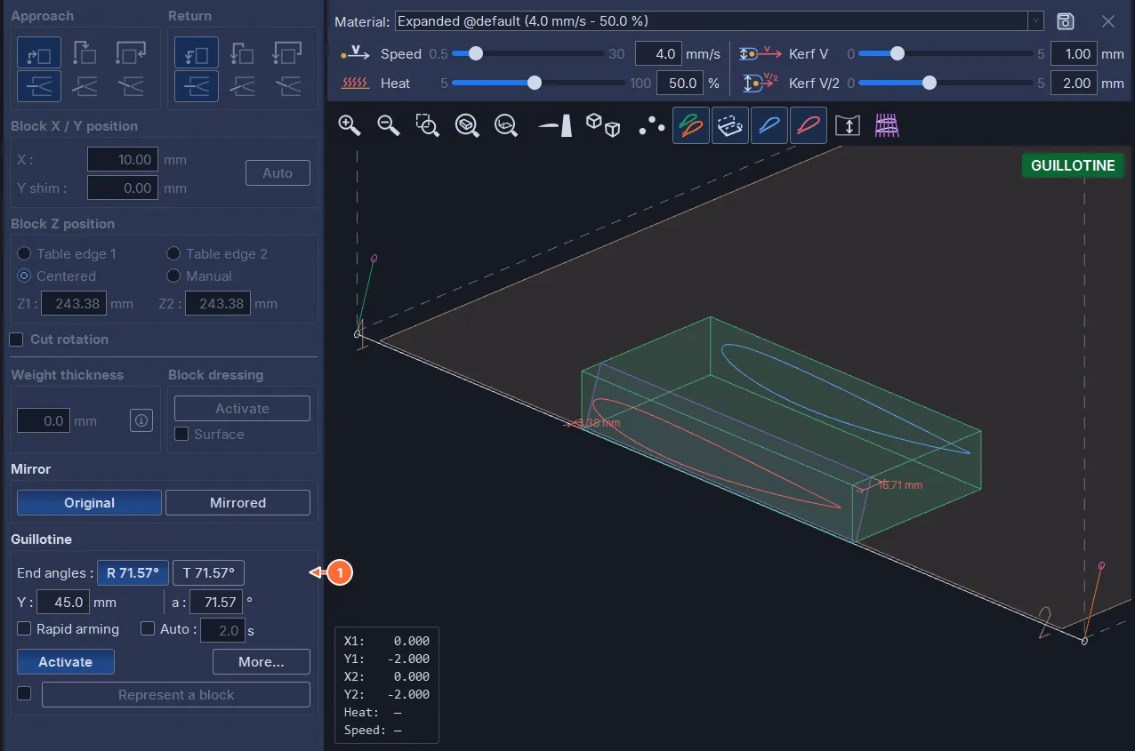
- End angles: the row only appears if the active document is a wing panel cut flat, rotated in its block (Wing › Cutting a panel flat). It carries one button per end to trim, R or T, with its angle, active only when the guillotine is activated. A pressed button writes a and Y (the thickness of the block plus the machine’s wire / block margin), and the 3D view shows the block laid for this cut: its end toward the wire origin, the cutting line across it, the profiles on its end faces, which tell on which side the leading edge goes, and two dimensions from the end face, one on the table up to the wire origin, along the leading edge, the other on the top up to the cutting line, along the trailing edge. With the Dimensions button, the laid block also gets the seven placement dimensions (see the dimensions): its entry corners are those of the end face, its exit corners those of the other end, which is thus set square. While a button is pressed, the Mirror frame stays active: Mirrored lays the block as a mirror image. Releasing the button, or deactivating the guillotine, gives a and Y back their previous values; typing in a releases the button and keeps the typed value; typing in Y leaves it pressed and the typed height is kept (the block and its cut do not depend on it).
A pause at the bottom of the cut (set in the machine) lets the wire finish melting before it is switched off. The settings that make no sense for a guillotine are grayed out while it is active, the cut rotation included.
5.15 Advanced guillotine and V/2 speed
More… replaces the left column with the advanced guillotine panel, which cuts a sheet into slices of equal thickness with a zigzag path: n + 1 horizontal traverses of length L, separated by n descents of e.
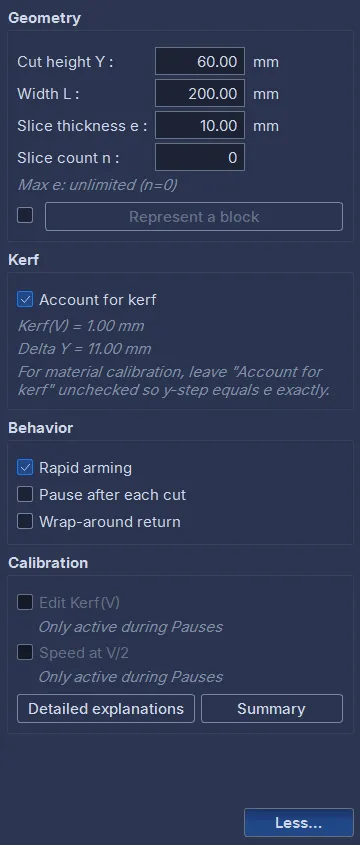
- Geometry: the cut height Y of the first traverse (0 = the top of the table), the width L, the slice thickness e, the number of slices n (n = 0: a single horizontal cut). The panel shows the maximum possible thickness for the chosen n. At the bottom of the frame, the Represent a block row, the same as in the simple guillotine and for the same block, draws the display block described above; the zigzag is then drawn on its faces.
- Kerf: Account for kerf raises the wire by half a kerf and lowers it by one extra kerf between two slices, so that each slice is exactly e after cutting. The panel recalls the kerf at V and the resulting vertical step.
- Behaviour: Rapid arming; Pause after each cut (the wire stops after each traverse, you start it again); Wrap-around return (when n is zero or even, the wire ends on the opposite side: it comes back at rapid speed over the block at the height Y_top, otherwise it comes back cutting at the last height).
- Calibration: Edit Kerf(V) unlocks the kerf slider of the banner so you can enter the measured value; Speed at V/2 halves the cutting speed for the rest of the cut. Both boxes are only active during a pause, with the machine stopped. Detailed explanations and Summary show the calibration procedure for a material, detailed in chapter 7.
When the window is too short to show everything, the four frames scroll; the row of buttons at the bottom stays visible. Less… returns to the normal configuration.
The path between the storage position and the origin is always traveled at cutting speed (too short to accelerate without risking the end stop); the last descent toward the table is at rapid speed.
On a GRBL interface, Speed at V/2 goes through a real-time setting of the board, which the board must confirm. Until it has done so, the button stays on Pause: Resume only appears after the confirmation. Without confirmation after 5 seconds, the “Speed not confirmed” window shows the value read and offers:
- Retry: sends the setting again;
- Back to V: unticks V/2, to let the cut finish at full speed;
- Stop the cut, the default choice, which acts like the STOP button (see “After a STOP”).
When the board no longer sends anything, the message becomes “The board no longer responds: check the USB cable and electrical interference.”.
5.16 Starting a cut
The Cut button, at the bottom of the right column, sends the cut to the machine over USB. Three conditions: the interface is recognized and compliant (green dot in the toolbar; an amber dot, board settings different from those of the machine, also refuses the cut, chapter 6), the license is active (chapter 16), and the cut passes the checks above.
Before clicking, the wire must be physically at the origin, in its storage position: the cut starts from there.
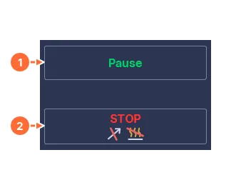
- Pause stops the movement, the wire stays hot; the same button becomes Resume.
- STOP, the word STOP above a crossed-out motion arrow and a crossed-out heat icon, is placed lower down to avoid an unfortunate click. It immediately stops the movement and the heat; the motors stay energized and the wire position stays exact. The “Cut stopped” window then offers what to do next (see “After a STOP”). The STOP button wired to the board has exactly the same effect.
The STOP button is not an emergency stop: it does not cut off any power supply. A true emergency stop cuts off the power to the motors and to the heat; it is wired on the machine.
Confirmation. A “Start cutting?” window summarizes the number of lines and the estimated duration, and reminds you to check that the wire is in its start position, that the block is properly positioned and weighted down, and that nothing obstructs the carriages. Just before the question, a colored line says how the approach will be made: in amber “‘Block dressed’ is ticked, the approach will run at rapid speed.”, in green “‘Block dressed’ is not ticked, the approach will run at cutting speed.”. This line does not appear for a guillotine nor for an approach from the top, where the box changes nothing. The default choice is No. On a laptop running on battery, a warning comes first: going to sleep in the middle of a cut ruins the part. During the cut, the computer does not go to sleep. On a GRBL interface, an alarm of the board is acknowledged automatically at the start; if it persists, or if a limit switch is pressed while the limit switches are enabled, the cut is refused and the message gives the cause.
Heat. The wire heats up while stationary, then the movement starts after the machine’s preheat time. On a GRBL interface, the heat is adjusted through a real-time setting of the board (an “override”), which the board must confirm; the status bar shows “Heating wire to …%” during this rise. The movement does not start until the heat is confirmed. Without confirmation after 5 seconds, the “Heat not confirmed” window gives the value read and the setpoint, and offers Retry or Stop the cut (the default choice). You must then check the $30 / $31 settings of the board and that its firmware accepts these real-time settings. When the board no longer sends anything, the message becomes “The board no longer responds: check the USB cable and electrical interference.”.
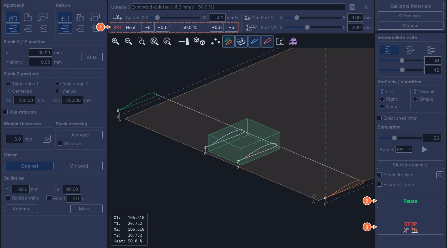
During the cut, the whole tab is locked and grayed out except the heat, Pause and STOP: the whole material row (the list, the floppy disk, ×), the three buttons of the banner, the left column, and in the right column the frames with their titles, Block dressed and its ⓘ. On a GRBL interface, only the heat slider changes: it gives way to four buttons −5, −0.5, +0.5, +5, with the icon and the word “Heat” remaining at the start of the row; the heat can thus be changed live without stopping the movement. On an IPL5X interface, the slider stays active. The HUD shows the heat read from the interface; if it stays away from the setpoint for 3 seconds, the line turns red with ⚠, and goes back to normal as soon as the setpoint is read. The status bar follows: preheat, cutting with the elapsed time over the total, pause, end.
Stop points. At a stop point or at an intermediate exit, the machine stops by itself, the wire on that point, and waits for Resume. Buttons wired to the board (STOP, pause, resume) act like the ones on the screen (chapter 6).
End. The wire goes back down into its storage position and switches off; the status bar shows “Cut complete.”. A sound marks the end of the cut and each stop, if it is enabled in the settings (chapter 3).
Cut interrupted. A cut stopped by something other than the STOP (an alarm of the board, a limit switch, the USB link lost, or a board that did not stop within 2 seconds after the STOP and that HotWire4X had to reset) opens the “Cut interrupted” window. It says in plain words what happened, what state the machine is in (the heat is off; after an alarm, the wire position is no longer certain) and what to do: always bring the wire back to the start position before starting again, for example with the Manual movement window. The code of the board (ALARM:… or error:…) is shown in small print, for support. The window can be moved without closing it: behind it, the view shows the wire where the machine stopped. Closing it puts the view back at the start.
Throughout the cut, the motors stay powered, pauses included, so that a carriage does not sag with the wire in the block. At the end of a complete cut, the motor setting of the machine applies at once.
On an IPL5X interface, the cut is refused if the PWM switch of the interface is on OFF or if a contact loop (Origin or End) is open; if the heat switch is on MANU, a confirmation reminds you of it. The cut is sent in sequences, split at each stop point: the wire switches off at a stop point (the wait can be long) and heats up again before moving off; a pause, on the other hand, keeps the wire hot.
5.17 After a STOP
A STOP during the cut, the one on the screen or the one wired to the board, stops the movement and cuts the heat without losing the wire position. On a GRBL interface, the board slows down then stops; on an IPL5X interface, the interface stops its pulses, and HotWire4X computes where the wire stopped from the remaining pulses. The rest of the cut is canceled and the Cut stopped window opens, surrounded by an amber frame to stand out from the 3D view. It leaves you the choice: resume the cut, move the wire by hand, go back to the origin or abandon.
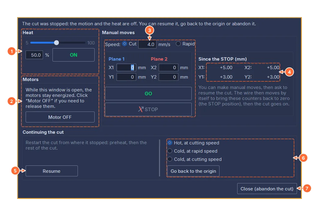
- Heat: the slider from 5 to 100 %, the field, ON / OFF and the state of the wire. This is the heat of the manual moves, of a hot return and of the rest of the cut. It starts from the heat of the cut; change it if the cut stopped because the wire was not heating enough.
- Motors: as long as the window is open, the motors stay energized, whatever the setting of the machine. Motor OFF releases them at once, to move the carriages by hand. The position is then no longer known: Resume and the return to the origin are grayed out, and a line recalls it. A move energizes the motors again.
- Manual moves: the speed (Cut, with its value, which starts from the speed of the material, or Rapid), then the relative moves in mm of Plane 1 (X1, Y1) and Plane 2 (X2, Y2), GO and STOP. This STOP, a crossed-out arrow, only stops the movement: the heat keeps its ON or OFF state. The movement and the heat only stop together with the STOP button of the board.
- Since the STOP (mm): the offset of each axis from the position of the STOP, tracked during the movement. Resume first brings the wire back to zero on these counters, then the cut continues.
- Continuing the cut: Resume, with what it does written above it (preheating, then the rest of the cut).
- The return to the origin: three modes and Go back to the origin.
- ((Close (abandon the cut))).
Resume. HotWire4X builds a new cut that starts from the stop point: the heat rises, the wire preheats in place (it leaves a small mark in the kerf, as at a stop point), then the cut continues. A cut stopped after the wire was switched off (the descent of a guillotine into the groove, for example) resumes cold. A STOP during the preheat, before any movement, makes the cut start again from the beginning. When resuming is not possible, a line under the button says why.
If the wire has been moved since the STOP, a “Back to the stop point” confirmation warns you first: the wire goes back in a straight line at cutting speed to the stop point, hot or cold as the cut was at that spot, and this straight line can cut a new passage through the block. When the stop point or the wire is in the storage groove, this return goes through the exit of the groove, which both sides travel together, vertically.
Go back to the origin. Three modes: Hot, at cutting speed (the default choice), Cold, at rapid speed and Cold, at cutting speed; a hot return at rapid speed is not offered. Each side goes in a straight line to the exit of the storage groove, both sides arriving together, then the wire goes down into the groove at cutting speed, both sides together: never one side in the groove and the other outside, the wire would catch on the edge. At rapid speed, the last 10 millimeters before the exit of the groove are made at cutting speed. Hot, the heat switches off before the descent. A cold mode first asks “Material removed?”: the wire must not meet the block on its path. During the return, the status bar shows “Returning to the origin…”, then “Back at the origin.”. A STOP during the return reopens the window, and Resume then brings the wire back to the stop point of the cut.
Close. ((Close (abandon the cut))) abandons the rest of the cut and gives the motors back the setting of the machine. Enter and Esc do not close the window, so that a cut is not abandoned by mistake.
An alarm during a manual move (a limit switch) makes the position unknown: resuming and the return to the origin are grayed out, as after Motor OFF. On an IPL5X interface, the same window opens after the STOP/PROG button of the interface or the STOP on the screen, including during a pause or at a stop point; the heat is controlled there directly, without confirmation from the board.
5.18 Exporting the G-code
On a GRBL interface, the Export G-code box replaces the Cut button with Export: the cut is written to a .gcode or .nc file, to be checked in a simulator or sent by another program. Export requires an active license.
The file contains a commented header: the file name of the saved workspace (without its folder; a workspace that was never saved is flagged as such), the machine, the two chords, the spacing, the block angle when the block is rotated, the duration, the speed and the heat. Then come the heat-up, then the movements in G93 (inverse time feed rate, which guarantees the synchronization of the four axes). The file also starts at the origin. It writes the heat setpoint directly, since another program does not adjust it in real time.
Show G-code, on the left of the status bar, replaces the left column with the G-code that would be sent to the interface, in color; the button becomes Show parameters to go back. The ⛶ button expands the G-code over the material banner and the 3D view, with the right column remaining accessible. Under the text, two lights come on when data goes out to the interface (→) or comes back from it (←), followed by the state of the board. Showing the G-code also requires a license.
These options do not exist on an IPL5X interface, which does not speak G-code.
5.19 Cleaning the wire
Clean wire, in the banner, starts a cycle that raises the wire to the machine’s cleaning height, heats it for the set time, then brings it back down at rapid speed. A “Clean wire” window summarizes the heat, the height and the wait, and warns that the movement starts as soon as you confirm; nothing must obstruct the carriages above the wire. The cycle reuses the guillotine (the frame is titled “Guillotine - Cleaning” and the view shows WIRE CLEANING during the operation) and gives the settings back unchanged afterward. Wipe the wire with a cotton cloth when it is in the high position.
Cleaning does not require a license. With Export G-code ticked, the cycle is written to a file instead of being sent.
The three values (heat, capped by the maximum power of the machine, height and wait) are set in the machine configuration (chapter 6).
5.20 Manual movement
Manual, in the banner, or the Machine ▸ Manual movement… menu, opens the Manual movement window, to move the carriages, heat the wire, check the direction of the axes, clear the wire or bring it back to the origin. The button is grayed out during a cut.
On the left, the heat and the Speed & moves frame, above the Communication log; on the right, over the full height, the Position & machine axes frame.
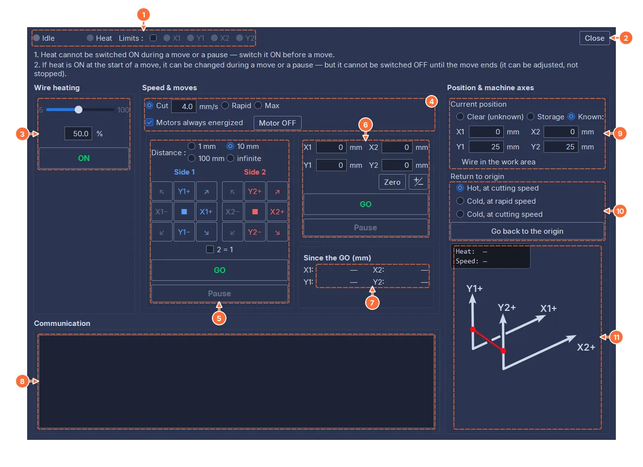
- The indicator lights: the state of the interface (“Disconnected” as long as it is not connected, otherwise the state reported by the board, Idle at rest), the heat actually applied to the wire and the limit switches, Limits (the box shows whether they are enabled in the machine configuration; one light per axis, bright red when the contact is pressed, dimmed red when the limit switches are disabled). On an IPL5X interface, two lights, Origin and End, show the two contact loops. On a GRBL interface, Rearm appears after them when the board is in alarm (see below).
- Close closes the window, like the cross in the title bar.
- Wire heating: the setpoint slider (from 5 to 100 %) and ON / OFF.
- The settings shared by both ways of moving: the speed (Cut, with its value in mm/s, Rapid or Max; on IPL5X, V, Vmax and Vmax accel.), the Motors always energized box and Motor OFF.
- Moving with the pads: the Distance, the Side 1 and Side 2 pads, the 2 = 1 box, then GO and Pause.
- Moving by values: the distances X1, X2, Y1, Y2 in mm, Zero and the sign inversion button (a ”+/−” key), then GO and Pause.
- Since the GO (mm): the distance traveled by each axis since the start of the last move.
- Communication: the log of the exchanges with the interface.
- Current position: Clear (unknown), Storage or Known:, the four fields of the wire position and, below them, the line that says where the wire is.
- Return to origin: three modes and Go back to the origin.
- The readout of the heat and the speed, and the diagram of the axis directions.
Heating the wire. On a GRBL interface, two rules are shown at the top of the window: the heat is switched on before a movement, not during it; once on, it can be changed during the movement but is only switched off at the end. ON heats the wire while stationary, and the slider gives way to four buttons −5, +5, −0.5, +0.5 that adjust the heat live. The two GO buttons and the pads stay grayed out until the board confirms the heat. Without confirmation after 5 seconds, the “Heat not confirmed” window offers Retry or Turn the heat off. During a movement, ON / OFF is grayed out; after the movement, the wire stays hot, and only OFF switches it off. If the heat read stays away from the setpoint for 3 seconds, the Heat line of the readout turns red with ⚠. The window always follows the board: when the board cuts the heat by itself (an alarm, the STOP button of the board), the heat is shown as off at once. On an IPL5X interface, the heat can be controlled at any time and the slider stays active; ON is refused as long as the PWM switch of the interface is on OFF.
The motors. The Motors always energized box keeps its state from one opening of the window to the next. Unticked, the machine’s motor shutdown delay applies: the axes become free again after a move and can be moved by hand, for example to set a zero. Ticked, it keeps the motors energized as long as the window is open, from the moment of connection, so that a pause or the end of a movement never releases them with the wire in the block; it is also the condition for tracking the wire position (see below). On a GRBL interface, the box acts at once: HotWire4X makes the motors do an imperceptible back-and-forth of one and a half steps, so that the board applies the setting. When the machine is configured with motors that are always energized, the box is ticked and grayed out: this is changed in the machine configuration (chapter 6). When the window closes, the setting of the machine is restored.
Motor OFF releases the motors right away, even those of a machine set to keep them energized at all times, to move the carriages by hand; the box and the setting of the machine stay as they are, and the next move energizes the motors again. The button is only active at rest: interface connected, no movement in progress and, on a GRBL interface, heat off.
Moving by values. Each field takes a relative, signed move in mm (the keyboard arrows change it, as in any numeric field); the two carriages finish their movement together. Zero sets the four values back to 0. The ”+/−” button inverts the sign of the four values, to repeat the same move in the opposite direction. GO starts the movement and becomes STOP to interrupt it.
Moving with the pads. The Distance is 1, 10 or 100 mm, or infinite. Each pad offers eight directions: X1+, X1−, Y1+, Y1− on side 1 (X2+, X2−, Y2+, Y2− on side 2), the names of the axes diagram, and the four diagonals; the central square clears the chosen direction. On a diagonal, the distance is that of the path, shared between the two axes. The 2 = 1 box makes side 2 follow the direction of side 1. With a finite distance, GO starts the movement like a move by values. With infinite, GO works while held down: the carriages move as long as the button is pressed and stop as soon as you release it.
Since the GO. The Since the GO (mm) frame gives, for each axis, the distance traveled since the start of the last move (by values, with the pads or continuous), with its sign, even when the wire position is unknown. The values follow the movement and stay displayed at its end; a dash before the first move and after a disconnection.
The wire position. The Position & machine axes frame tracks the wire position, to avoid wrong moves: leaving the storage groove at an angle, going below the table, exceeding a travel limit. Current position offers three choices:
- Clear (unknown), the choice on opening: the wire is clear but its position is unknown; nothing is checked and the fields show a dash;
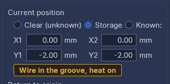
- Storage: the wire is at the bottom of the storage groove, on both sides (X = 0, Y = the depth of the groove, as a negative value);
- Known:: the wire position is entered in the four fields. A position outside the allowed zones is refused by the “Position refused” window, which gives the reason, for example “This position is outside the machine’s X travel.”.
Once declared, the position follows each move: the fields show the wire position, read from the board (GRBL) or counted in steps (IPL5X), and a move from the storage position switches to Known:. Under the fields, a line says where the wire is: “Wire in the work area” or “Wire in the groove”. If the wire is in the groove with the heat on, this line becomes an amber banner, “Wire in the groove, heat on”: it is a reminder, nothing happens automatically.
Tracking the position requires motors that are held: as long as the Motors always energized box is not ticked (on a machine that does not keep its motors energized), Storage and Known: are grayed out and a gray line recalls it. The position is lost, and goes back to Clear (unknown), every time the wire may have moved without HotWire4X knowing: motors released (box unticked, Motor OFF), an alarm during a move, the board restarted, the interface disconnected; on IPL5X, a limit switch or a sensor, the link lost, or the abrupt stop of a movement faster than the speed without acceleration. The log writes it, for example “Wire position lost (motors released): declare it again.”.
The checks. With a known position, each move must stay within a single zone: the work area (above the table, within the X and Y travel of the machine) or the groove (X = 0 on both sides, from its bottom up to the top of the Y travel). Clear (unknown) checks nothing.
- A GO that would take the wire out of its zone, by values or with the pads at a finite distance, opens the “Move refused” window, which gives the reason, for example “The wire is in the groove: it must first leave it vertically (X = 0).”. Nothing is sent to the machine and nothing is corrected automatically.
- On the pads, each direction that would take the wire out of its zone is grayed out and loses its color. With a finite distance, the whole distance must fit; with infinite, a little room is needed in that direction.
- The continuous move (infinite) stops by itself at the limit of the zone.
The speeds, for their part, stay free.
Return to origin. The three modes are those of the “Cut stopped” window: Hot, at cutting speed, Cold, at rapid speed and Cold, at cutting speed. Go back to the origin takes each side in a straight line to the exit of the groove (X = 0, Y = 0), both sides arriving together, then lowers the wire into the groove at cutting speed; at rapid speed, the last 10 millimeters are made at cutting speed. The speeds are those of the window: the value of the Cut field and the rapid speed of the machine.
The return requires a known position and held motors, at rest; as long as the position is Clear (unknown), the button is grayed out and its tooltip says why. A confirmation precedes the movement: hot, it warns that the straight line can carve a new passage through the block; cold, it asks “Material removed?”. A hot return with the heat off first switches the wire on at the heat of the window and waits for the machine’s preheat; hot, the heat switches off at the exit of the groove, before the descent. A cold return with the heat on first switches it off. During the return, the button becomes STOP. On arrival, the position switches to Storage; stopped on the way, the wire stays in the Known: position, where it is. If the wire is already in its storage position, a message says so: “The wire is already at the origin.”.
Pause and stop. On a GRBL interface, each move frame has its own Pause, active for the movement it started; the button becomes Resume during the pause. It stays grayed out during an infinite move, which stops when GO is released. STOP interrupts the movement and keeps the wire hot. On an IPL5X interface, STOP stops a movement that has an acceleration ramp by running back down its ramp, without losing any steps: the wire position is kept. A movement without a ramp stops abruptly, like a second STOP during the ramp; above the speed without acceleration, this abrupt stop can lose steps, and the position is lost. A movement is refused when no distance is entered, when no direction is chosen on the pads, or when a limit switch is pressed while the limit switches are enabled.
The STOP button of the board stops the movement and cuts the heat. Outside a cut, HotWire4X hands control back at once, without any window: the movement ends, the heat is shown as off and the board accepts the next command. The wire position is kept, and Go back to the origin stays available.
Rearm. On a GRBL interface, Rearm, in red, only appears when the board is in alarm and at rest (a limit switch, a movement interrupted by a restart of the board): it clears the alarm, without any movement and without ever starting a homing cycle. A GO, a move with the pads or ON also clear the alarm before acting; Rearm is used to clear it without commanding anything. If the board stays in alarm, the “Alarm not cleared” window gives the cause, for example “The STOP button is still pressed. Release it, then click Rearm.”.
The readout. Under the position, a box gives the heat read from the interface and, during a movement that is identical on both sides, the speed; a dash otherwise. The diagram, below it, recalls the positive direction of each axis.
As long as the wire is heating or a movement is in progress, the computer does not go to sleep. Closing the window in this state asks for confirmation: Stop & close stops everything first.