The Wing tab builds a complete wing, in one or more panels, from wing profiles and a few dimensions. It adds the structural elements (spar, hinge, sheeting, kerf, X cut of the leading edge), defines each panel’s block, then transfers each panel, or the whole wing at once, to Design and Cutting as documents with two synchronized paths. Everything the Design tab does remains possible afterward on the transferred document.
The screenshots in this chapter show the inverted gull wing of the Corsair from the example Corsair F4U.hw4x, supplied in the library (three panels, an aileron hinge, a reference plan).
8.1 The Wing tab
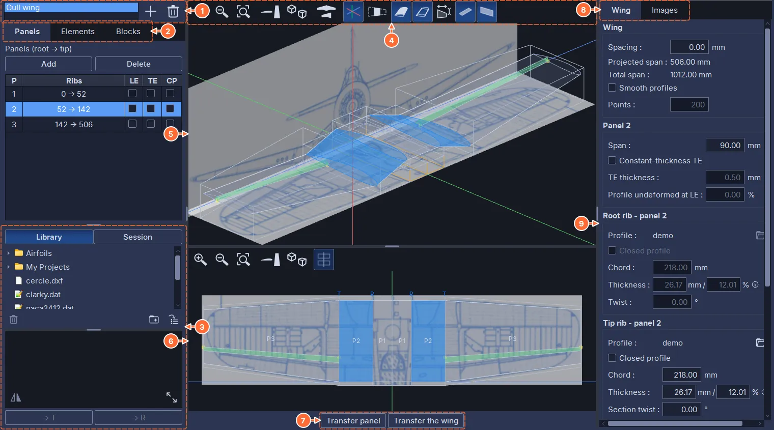
- The list of the workspace’s wings, with + and the trash can: a project can hold several wings (the wing, the stabilizer and the fin of the Caudron example,
Caudron C450.hw4x). A double-click renames. - The three sub-tabs of the left column: Panels, Elements, Blocks. Each shows its list on the left and its editor on the right.
- The library (chapter 4), the same as in Design and Views, with its Library | Session switch and its two buttons → T and → R, which assign the selected profile to the outer rib or to the inner rib of the active panel.
- The toolbar of the upper 3D view; its display buttons act on both views.
- The upper 3D view: the whole wing, the ribs, the envelope between them, the elements, the blocks. The active panel is tinted.
- The lower 3D view, opened in top view, with the number of each panel (section 8.5).
- Transfer panel: the active panel becomes a cutting document; Transfer the wing does the same for every panel.
- The two sub-tabs of the right column: Wing (the editor of the panel, element or block selected on the left) and Images (the background images).
- The editor of the active panel.
The left column collapses completely when its handle is dragged to the edge of the window, and comes back the same way; the center column and the right column do not collapse. The wing’s coordinate system is the cutting one: X along the chord, Y vertical, Z along the span. The status bar shows the active panel and the number of panels, and reminds you that a click in either view selects a panel.
8.2 A wing in panels
A wing half is a series of panels, numbered from the inside out to the tip, from one to twelve. Two neighboring panels share their junction rib: the profile, the chord and the twist of a panel’s last rib are those of the next panel’s first rib, and are entered only once. In each panel, the inner rib is marked R and will become side 2 (red) of the cut; the outer rib is marked T and will become side 1 (blue). These two letters come back on the library buttons, in the twist (Twist T), in the (R) and (T) labels of the elements and blocks, and in the lower view; the panels themselves are marked P1, P2… in the lower view. Each panel will be cut in its own block.
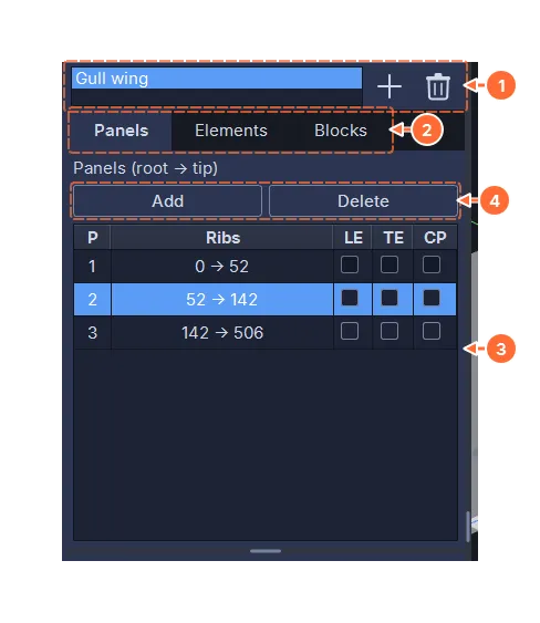
- The wing list: + creates a wing (a name is asked for), the trash can deletes the selected wing; if it already has transferred panels, the software offers to delete them too or to keep them as free documents.
- The Panels / Elements / Blocks sub-tabs.
- The table of the active wing’s panels, from the inside out to the tip: P, the panel number; Ribs, the position of its two ribs in millimeters from the wing’s first rib; the LE, TE and CP boxes, which concern the rib the panel shares with the previous one (see below). Clicking a panel makes it the active panel, also selected in the 3D views and the editor.
- Add inserts a panel after the selected panel, with the same profile, a span of 200 mm and no sweep, dihedral or twist; Delete removes the selected panel (deleting the first panel makes the next rib the new inner rib).
The 3D views show both wing halves; the wing is built once, the left side is the mirror image of the right.
8.2.1 Aligning the edges and computing the profiles
A wing made of a single trapezoid often has to be built in several panels: a wing-joiner bay near the fuselage, an aileron zone toward the tip. Each change of zone is a rib, since the wire cuts a ruled surface from one rib to the next. The table’s three boxes keep this division from changing the shape of the wing. Checking a box on a panel says that the rib shared with the previous panel is not a corner of the wing; consecutive checked panels form a group.
- LE: the group’s leading edge is a single straight line; the group’s sweep is split between its panels in proportion to their spans.
- TE: the group’s trailing edge is a single straight line; the chord of the ribs inside the group is computed, the two end ribs stay free.
- As soon as LE or TE is checked, the twist is also spread over the group. The dihedral is never constrained, and the profile and thickness of the interior ribs stay free.
- CP (computed profile): the shared rib no longer has a profile of its own; its profile is computed from the group’s two end ribs (Design’s intermediate profile, chapter 4), at the rib’s chord. The editor then shows Computed instead of the profile name. The imported profile is kept and comes back when the box is unchecked.
Computed fields are grayed out and show their value; to edit such a rib, uncheck the box of the next panel. In both 3D views, a rib inside a group is drawn dotted. The boxes on the first row of the table are grayed out: the first panel has no previous panel.
8.3 Panel parameters
The editor in the right column (sub-tab Wing, when Panels is selected on the left) shows, from top to bottom:
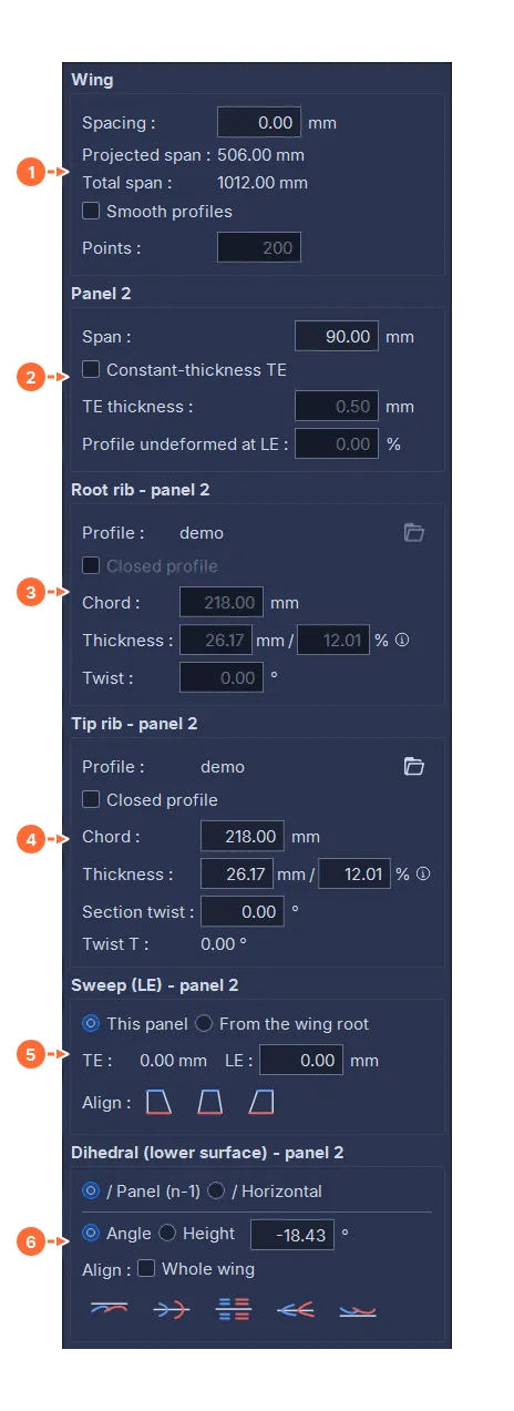
- Wing: the spacing is the width of the fuselage, that is, the space left between the two wing halves; below it, the projected span and the total span of the complete wing (read-only). Smooth profiles rebuilds each rib on a smooth curve through its own points, with the number of Points given (200 by default, from 40 to 500): an old profile, defined by few points, loses its facets, which the cut, the kerf offset and the sheeting would otherwise inherit. The curve passes exactly through the profile’s points, the trailing edge stays sharp and the chord does not change; the stored profile is not modified, so the option can be unchecked without loss. The setting applies to the whole wing. Leave it unchecked for a profile made of straight segments, which it would round off.
- Panel n: the panel’s span, the distance between its two ribs. The Constant-thickness TE box opens the trailing edge of both ribs to the TE thickness given (a sharp trailing edge cannot be cut with a hot wire); the camber is kept; 0 mm closes the trailing edge back to a point. Profile undeformed at LE sets the fraction of the chord, from the leading edge, that keeps the original profile exactly: the opening starts at that position and grows up to the trailing edge (0 %: the whole profile opens as a wedge from the leading edge).
- Root rib - panel n (the inner rib, R): the profile name and a folder button to load another one; the Closed profile box (see below); the chord; the maximum thickness, in millimeters or as a percentage of the chord (the two fields are linked; changing the value thins or thickens the profile while keeping its camber and its chord, like XFOIL’s THKCAM command; the ⓘ at the end of the row says so); the twist of this rib. The thickness is that of the finished rib, trailing-edge opening included. From panel 2 on, this rib is the previous panel’s: its fields are grayed out, and it is edited in the previous panel.
- Tip rib - panel n (the outer rib, T): the same fields, plus the Section twist (the angle added between the two ribs); Twist T gives the total twist of this rib (read-only). The twists add up from panel to panel.
- Sweep (LE): at the top of the frame, the scope, which applies to the whole frame: This panel (the local sweep, the panel’s outer rib relative to its inner rib) or From the wing root (the global sweep, relative to the wing’s first rib); a local sweep carries the following panels along, a global sweep leaves them in place. Below, TE: the trailing-edge sweep, computed from the leading-edge sweep and the two chords, twist included (read-only), and LE: the leading-edge sweep, the setback of the outer rib’s leading edge, the only editable value. Under Align, the three buttons set the LE sweep so that the trailing edge, the mid-chords or the leading edge has no sweep, in the chosen scope; the value stays editable afterward. In a group with an aligned leading edge (LE box), the frame is titled “Sweep (LE) - panels a-b”, the local scope becomes These panels and the values are those of the whole group; on a rib inside the group, the value and the three buttons are grayed out. The scope also sets the sweep dimensions (section 8.5).
- Dihedral (lower surface): the choice / Panel (n-1) or / Horizontal, at the top of the frame, applies to the whole frame, and to the dihedral dimensions too (section 8.5). The dihedral is entered as an Angle or as a Height (the height difference between the two ribs), always measured on the lower surface, relative to the previous panel or to the horizontal. Under Align, the five buttons set the dihedral so that a line of the profile (the bottom, the top, the center, the leading edge or the trailing edge) is horizontal on this panel (/ Horizontal) or continues the previous panel’s line without a break (/ Panel (n-1)); the value stays editable afterward. The Whole wing box applies the alignment to every panel; with / Panel (n-1), the first panel keeps its dihedral and the chosen line becomes a single straight line, at the first panel’s slope.
The Closed profile box closes the rib’s trailing edge: the wire also cuts its back face, between the last and the first point of the profile (the flat back of a fuselage, a thick trailing edge). It checks itself when a closed contour with a flat back is imported, for example a fuselage side view exported from the Views tab, and unchecks itself when any other profile is imported. A sharp trailing edge is already closed. A panel’s cut is closed as soon as one of its two ribs is. Like the folder button, the box is grayed out on a rib that belongs to the previous panel; a rib with a computed profile (CP box) is closed as soon as one of the end ribs of its group is.
Changes are applied when the field is confirmed (Enter or Tab) and show at once in both 3D views. All numbers are in millimeters and degrees. When no panel is selected (after a click on empty space, section 8.5), the panel frames are grayed out; the Wing frame stays editable.
8.4 Loading the profiles
Each rib receives a wing profile: a library file (.dat, .cor, .dxf, .svg, .txt, or a .hw4x / .fnx project from which one side is taken) or a profile of the open project. There are three ways to load it:
- select the profile in the library, then click → T (the outer rib) or → R (the inner rib); → R is grayed out when the inner rib belongs to the previous panel, → T when the rib’s profile is computed (CP box of the next panel), both when no panel is selected;
- the rib’s folder button, in the editor, which opens a file dialog; a file that cannot be read, or that contains no path, is reported;
- for a file that contains several paths, the selection dialog of chapter 4 lets you choose the profile.
The library is the same browser as in Design and Views (chapter 4): the file tree, which you reorganize by drag and drop and in which F2 renames an item, the preview with its mirror and enlarge buttons, and the file-management row under the tree. The Library | Session switch, at the top, replaces the files with the profiles of the open project: the Design documents, the Views outlines, the ribs of the wings (R1, R2… from the first rib) and the sections of the Sections tab; the same buttons import them, as copies. Under Elements, when the active element is a spar, the two buttons give way to → Spar profile (section 8.6).
A rib profile is a wing section: the outline starts at the trailing edge, follows one surface to the leading edge and comes back to the trailing edge along the other surface. A closed contour (drawn in CAD, for example) is accepted whatever its starting point; an outline that does not follow this shape is refused, with the reason. A .dat, .cor or .txt profile is scaled to the rib’s chord, which does not change. A profile in millimeters (a .dxf or .svg drawing, a project document, a session profile) keeps its size: the rib’s chord becomes the profile’s, so a fuselage side view keeps its length. The preview’s mirror button flips the profile before the import (a profile drawn the other way round). As in Design, the leading edge is on the right (Xmax) and the trailing edge on the left.
The two ribs of a panel can have different profiles, with different numbers of points: the 3D views then synchronize the two profiles to draw the envelope, as the transfer to Design will (section 8.9 and chapter 4).
8.5 The two 3D views
The center column shows the wing in two stacked 3D views. They draw the same scene: the display buttons of the upper toolbar act on both views, and each view keeps its own camera. The lower view has a reduced toolbar and opens in top view.

- Zoom in, zoom out, fit to view.
- The view cycle: side (the profile, leading edge on the right), top (the span horizontal, leading edge at the top) and front (seen from the leading edge, which shows the dihedral); then Ortho / 3D view, which returns to the three-dimensional view and switches from orthographic projection to perspective.
- The wing halves: both, the left one only, the right one only. With a single wing half at the top, the lower view shows the other one.
- The axes: X in green along the chord, Y in red vertically, Z in blue along the span. They cross on the aircraft’s centerline, level with the rearmost point of the wing, at table level (section 8.8).
- Single panel: show only the active panel, with its elements, its block and its pre-cut.
- The envelope of the profiles between the ribs; hiding it leaves the element envelopes on their own.
- The overall outline (the silhouette, CAD style).
- The dimensions, off at first: those of the panels (below) and those of the active element (section 8.6).
- The plan view image: the plan of the wing, laid flat at table level, under the wing, in both views (section 8.8).
- The free images (chapter 12).
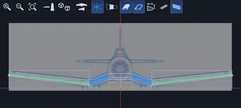
The mouse works as in Design: mouse wheel to zoom, middle button or Alt + left button to rotate, right button to pan. In the side, top and front views, the orientation is fixed and the rotation gesture pans the view.
8.5.1 The lower view
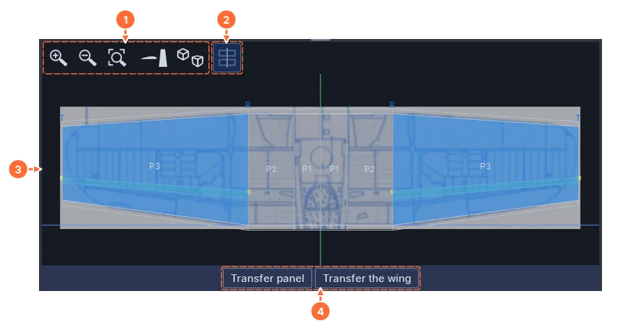
- Its toolbar: zoom in, zoom out, fit to view, the view cycle and Ortho / 3D view.
- The button that links the two views, on at first: as long as both views are in side, top or front view, they have the same zoom and, when both run along the span (top view and front view), the same left-right framing, so that the ribs of the two views line up one above the other. A zoom or a pan in one view carries over to the other, and fit to view frames both together. The button is grayed out when either view is in 3D.
- The lower view, in top view, leading edge at the top: the number of each panel (P1, P2…) and, above the leading edge of the active panel, the letter of each rib, R for the inner rib and T for the outer rib. A panel that will be cut upside down (section 8.6) has its number in orange, and its leading edge and trailing edge in orange in both views. Move in the Images sub-tab lets you drag the plan view image there (section 8.8).
- Transfer panel and Transfer the wing (section 8.9).
The lower view collapses when the handle that separates it from the upper view is dragged all the way down; the transfer buttons then stay under the upper view.
8.5.2 Selecting with a click
A click, without dragging, in either view selects what the left sub-tab edits: a panel under Panels and Blocks, an element under Elements. The active panel is drawn with its two ribs in the accent color and its surface tinted, readable even under a total sheeting. Under Blocks, the click only selects the panel: a block is shown or hidden by its Show box. Under Elements, a sheeting always comes last, since it wraps the wing: a click on a spar through the sheeting selects the spar.
A click on empty space, under Panels or Blocks, deselects the panel: no more tinted panel or selected row in the tables, the panel and block frames grayed out, Transfer panel and the library’s import buttons inactive. A click on a panel or on a table row selects it again. Under Elements, a click on empty space changes nothing.
8.5.3 Panel dimensions
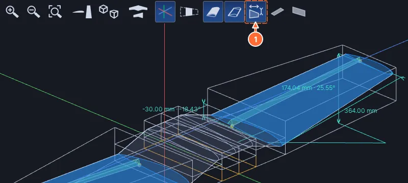
- The dimensions button.
Under Panels, the dimensions button adds the dimensions of each panel, in turquoise, at its outer rib:
- the sweep, along the chord, from the leading edge of the reference rib to the leading edge of the outer rib; its extension line, along the span, carries the span. The reference follows the scope of the Sweep (LE) frame: with This panel, the panel’s inner rib (the value is the panel’s sweep, the extension line carries its span); with From the wing root, the wing’s first rib (the sweep and the span from that rib);
- the dihedral, vertical, a little behind the trailing edge of the outer rib, from the reference level to the lowest point of that rib; it shows the height and the angle. The reference level follows the scope of the Dihedral (lower surface) frame: with / Horizontal, the horizontal through the lowest point of the inner rib; with / Panel (n-1), the plane of the previous panel, extended. With / Horizontal, a second dimension also gives the height of the outer rib’s lowest point above that of the wing’s first rib.
A dimension seen end-on is not drawn: the top view shows the sweeps, the front view the dihedrals. A zero value has no dimension. Under Elements, the same button shows the dimensions of the active element (section 8.6); under Blocks, it is grayed out.
8.6 Structural elements
An element is a cut added to the profile, over part of the span or over the whole wing: a spar slot, a hinge groove, a kerf groove, an X cut at the leading edge (the X LE), or a sheeting (the profile is reduced by the thickness of the skin that will be glued onto it). The tab draws these elements in the 3D views and builds them into the cutting path at transfer time.
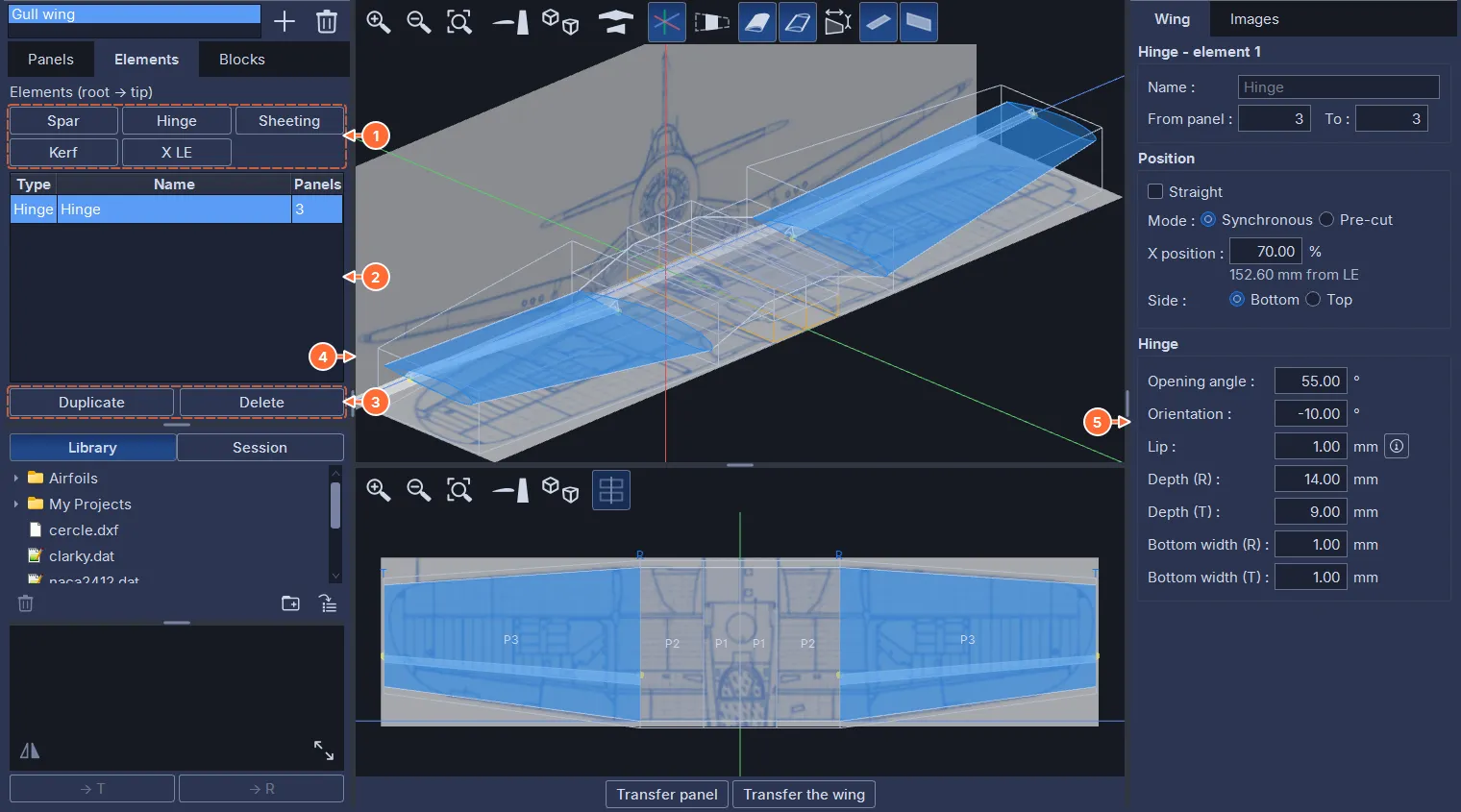
- The creation buttons, one per type: Spar, Hinge, Sheeting, Kerf, X LE. A new element covers the whole wing. Sheeting is grayed out as soon as a total sheeting exists.
- The element list: the type, the name, the panels covered. Clicking an element, in the list or in a 3D view, shows it in the editor.
- Duplicate and Delete the selected element.
- The 3D view draws each element in its color, as an envelope between the ribs, the active element in white; a small marker shows its entry point on each rib.
- The element editor.
A new element has no name: the list and the editor show it under the name of its type, in the interface language. Typing the type name in the Name field amounts to giving no name; a name chosen by the user is kept as is.
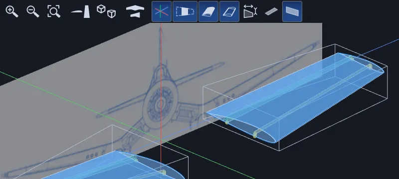
8.6.1 Common parameters
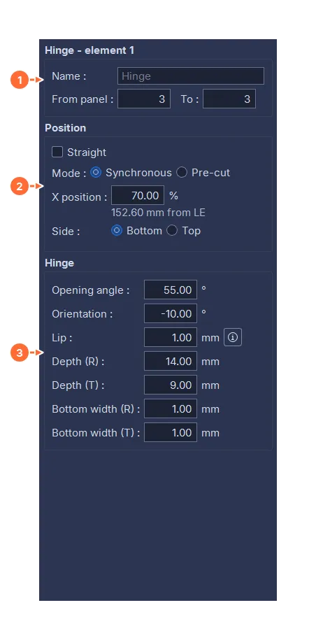
- The element’s Name and its range: From panel … To. An element can cover a single panel or several consecutive panels.
- Position:
- Straight: the element is a straight line in space between its two ends (a tube spar, a rigid hinge) instead of following the profile of each rib; the dihedral of the intermediate ribs is ignored;
- Synchronous (spar) or Mode: Synchronous / Pre-cut (hinge, kerf): a synchronous element is at the same position on every rib and is cut with the profile, in the same pass; the pre-cut is described below. A straight hinge or kerf is necessarily a pre-cut;
- X position: the position of the element along the chord, as a percentage of the chord measured in X from the leading edge of the finished rib (0 % at the leading edge, 100 % at the trailing edge). The finished rib is the one that will be cut, constant-thickness trailing edge included; a sheeting does not change it. The element enters through the surface at that X: through the highest point of the profile for an entry from above, through the lowest for an entry from below. Under the field, the software shows the same position in millimeters from the leading edge (”… mm from LE”). A synchronous element has a single field; otherwise the position is entered at both ends of its range, X position (R) and X position (T), and the software interpolates between the two along the span;
- Entry: Upward / Downward (spar, kerf) or Side: Bottom / Top (hinge): the wire enters from below (the lower surface) or from above (the upper surface).
- The dimensions specific to the type; those that can vary along the element are entered at both ends of its range: (R) for the inner rib of its first panel, (T) for the outer rib of its last panel.
An element is cut by the wire, which enters through the surface, goes around the shape and comes back out the same way: the way in and the way out are junction paths (no kerf compensation, chapter 5), and the outline of the shape is offset by the kerf like the rest of the profile. A hinge and a kerf groove end in small lips: two small points of material that the wire’s path leaves at the opening of the groove, one on each side. They keep the cut inside the profile and absorb the wire’s excess heat; the waste shell is thus barely deformed at that spot and holds the sheeting well when it is used to press the sheeting onto the core. The Lip value is the distance, measured along the wall of the groove, between the profile surface and the point where the lip meets the wall; the ⓘ button at the end of the row opens the Lips window, which explains it.
8.6.2 Spar
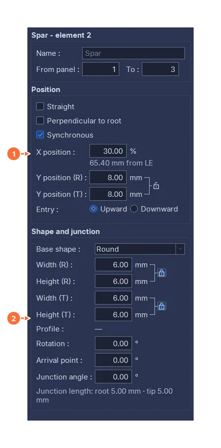
- Position, in addition to the common parameters:
- Perpendicular to root places the slot so that a straight wing joiner crosses the fuselage at right angles, even on a swept wing: with Straight unchecked, only the spar’s first panel is perpendicular; checked, the whole spar forms a single perpendicular rod;
- Synchronous; when the box is unchecked and the two positions differ, the Link between the surface and the slot is either Oblique (the junction is tilted so as to enter at the same place on both ribs; the software shows the resulting tilt and flags it in red beyond 40°, where the pre-cut is required) or Pre-cut;
- the X position places the center of the spar’s box (the rectangle around it);
- Y position (R) and Y position (T) place the spar in height: the distance between the entry surface, vertically in line with the center, and that center. A rotation or a change of size leaves the center in place. The two rows are joined by a bracket and a padlock, like the width and the height of the shape. Open (at first), each end is set freely. Closed, both ends keep the same value: when it is closed, Y position (T) takes the value of Y position (R), then changing one changes the other;
- Shape and junction:
- Base shape: Round, Square or Imported profile; while Imported profile is chosen, a hint recalls where the profile comes from: select it in the library of the left column, then click → Spar profile at the bottom of the column. The points of the imported profile are kept as they are, only scaled to the width and the height; Profile gives its name;
- Width and Height at each end, (R) then (T), joined by a bracket that carries a padlock. Closed (at first), the padlock keeps the ratio between the two values shown: changing one changes the other. Open, they are set freely. Another base shape or another imported profile starts again from its own proportions (1 for the round and the square);
- Rotation: turns the shape about the center of its box; a positive value raises its leading-edge side. The width and the height are those of the shape before rotation;
- Arrival point: where the junction meets the spar, as an angle about the center; 0 is vertically in line with the center, on the entry-surface side, and a positive value turns toward the leading edge. The point turns with the spar’s rotation; a pre-cut plunges vertically to it;
- Junction angle: the tilt of the junction from the vertical, a positive value leaning its surface entry toward the leading edge; only for a synchronous spar that is neither Straight nor Perpendicular to root;
- below, the junction length at both ends, a result (hidden for a pre-cut).
When the spar tube comes out of the profile on a rib, in any mode, the editor says so in red, with the remedy: adjust the position or the size, or switch to pre-cut (for a synchronous spar, uncheck Synchronous, then choose Pre-cut). It is a warning: it does not prevent the transfer.
8.6.3 Hinge
Opening angle of the V groove, Orientation (the tilt of the groove relative to the normal to the profile, for an offset hinge), Lip, Depth (R) and (T), Bottom width (R) and (T) (width 0 = a sharp V, otherwise a flat bottom). A hinge sits at 70 % of the chord by default, and its depth is proposed in proportion to the chord.
8.6.4 Kerf
A narrow flat-bottomed slot, to house a strip, a rod, a pushrod. The Dimensions frame gives the Angle of the slot relative to the normal to the profile, the Vertical kerf box, the Height (R) and (T) (the depth of the slot), the Width (the gap between its two walls) and the Lip.
Vertical kerf computes the angle on each rib so that the walls of the slot are vertical in the cut, whatever the slope of the surface and the twist of the rib; the height is then a vertical depth. The angle varies from one rib to the next: the Angle field, grayed out, shows that of the (R) rib, and a line under the box gives the angles at both ends. The angle entered by hand is kept and comes back when the box is unchecked.
8.6.5 Sheeting
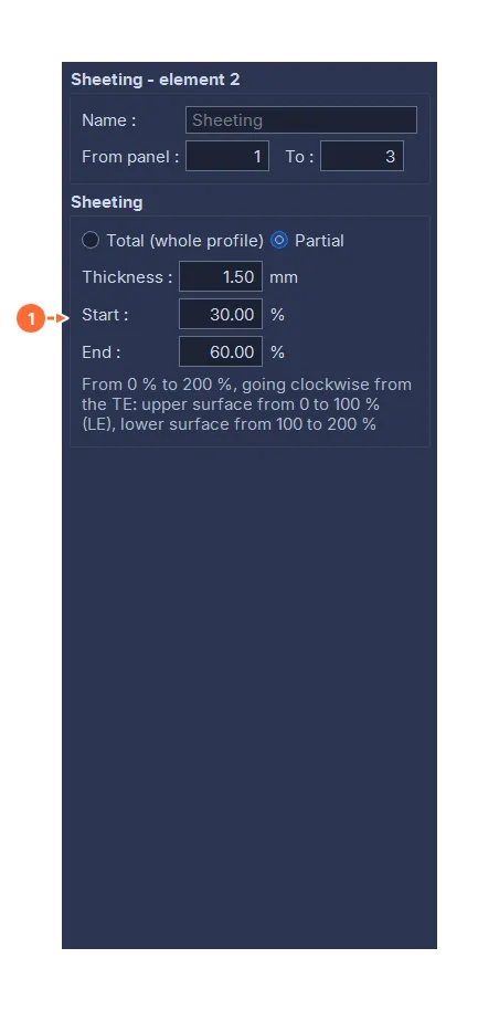
- Total (whole profile) or Partial; the Thickness of the skin (the profile is offset inward by this value, with Design’s offset tool). A partial sheeting adds the Start and the End of the band, as a percentage of the contour, and the hint that explains them: from 0 to 200 % going clockwise from the trailing edge, the upper surface from 0 to 100 % (the leading edge), the lower surface from 100 to 200 %. A band from 70 to 130 % thus covers the leading edge on both faces. For a total sheeting, these rows disappear.
Only one total sheeting per wing, and no total sheeting together with partial bands; partial bands cannot overlap, and the software readjusts them. The other elements are cut in the sheeted profile; their X position is still measured on the finished rib, so a spar at 30 % stays at 30 % of the chord of the finished wing, whatever the sheeting.
8.6.6 X LE
A diamond-shaped cut in the leading edge, to glue a separate leading edge into: the Angle of the roof, the Width and the Height of the diamond, the Height proportional to chord box, its Orientation and its Position (as a percentage of the contour, like a partial sheeting; 100 %, the default value, is the leading edge). The dimensions are the same over the whole span; with the box checked, the height entered applies to the inner rib of the element’s first panel, and every other rib gets it multiplied by the ratio of its chord to that rib’s chord; the width does not change. Its points stick out of the profile: the block and the chord are computed on the profile alone.
8.6.7 Element dimensions
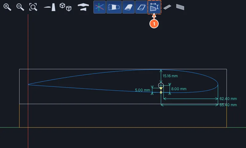
- The dimensions button.
Under Elements, the toolbar’s dimensions button shows the dimensions of the active element, and of that element only, on its two end ribs, where its (R) and (T) values are entered. They are measured on the shape the wire cuts:
- the X position, horizontal, from the leading edge of the finished rib to the element’s point: the center of a spar’s box, the entry point of a hinge or a kerf; it is placed above the profile for an entry from above, below it for an entry from below;
- for a spar, in addition: the X gap between the leading edge and the frontmost point of the spar; the Y position, from the entry surface to the center, and the gap between the surface and the nearest point of the spar; a cross on the center and a line from the center to the junction’s arrival point;
- for a spar, the thickness of material on the side opposite the entry: from the highest point of the spar up to the profile above for an Upward entry, from the lowest point down to the profile below for a Downward entry, vertically from that point. When the spar breaks through that surface, the value is negative and the dimension turns red.
A sheeting and an X LE have no dimensions. With Single panel, only the dimensions placed on a rib of the active panel remain.
8.6.8 The pre-cut
A pre-cut element is cut in a separate first pass, before the profile: the wire plunges from the top of the block, cuts the shape and comes back up, as many times as there are elements, then cuts the profile normally. The profile is thus never deformed by the element’s entry. Setting an element to pre-cut shows the blocks of all the panels, since the pass starts from the top of the block. In return, the panel is cut in a fixed orientation, that of the entry; an element that enters from below means the panel must be mounted upside down on the machine: in both 3D views, its leading edge and trailing edge are drawn in orange (its number too, in the lower view), and the notice ”⚠ Panel(s) cut upside-down” appears under the views. All the pre-cut elements of a panel enter through the same face; changing the side of one offers to change the others.
8.6.9 Feasible and infeasible elements
The wire passes at the same time through the points with the same number on both sides: the two ribs of a panel must therefore carry the same elements, in the same order along the profile. When this is not the case, the red message ”⚠ Elements out of order between the two sections — transfer disabled” appears under the views and Transfer panel is grayed out; moving the offending element is enough. A spar’s editor also flags in red an oblique link that is too steep and a tube that comes out of the profile, and the 3D views draw the junction concerned in red; these warnings do not prevent the transfer.
8.7 The blocks
Each panel is cut in its own block. The Blocks sub-tab defines them.
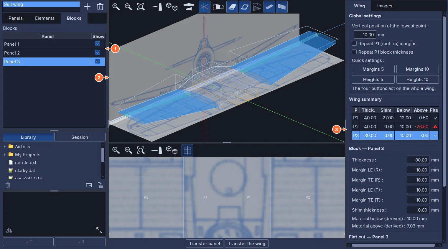
- The panel list, with a Show box per block to draw it in the 3D views. Clicking a row, or a panel in a 3D view, selects the panel; only the box shows or hides a block.
- The blocks in 3D: a prism around each panel, and its shim.
- The blocks page, in the right column.
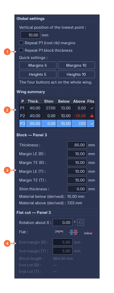
- Global settings, valid for the whole wing:
- Vertical position of the lowest point: the material under the lowest point of the wing; the block of that panel rests on the machine table;
- Repeat P1 (root rib) margins (the root rib is the R rib of P1, its inner rib): every margin of the wing, P1’s outer rib included, takes the two margins (LE and TE) of that rib; as long as the box is checked, no other margin can be set, and the other margin fields are grayed out;
- Repeat P1 block thickness: every block takes P1’s thickness; set on the table, they share the same top, and their top waste shells line up from one panel to the next. The other thickness fields are grayed out; the shims stay free;
- Quick settings: Margins 5 and Margins 10 set every margin of the wing to 5 or 10 mm. Heights 5 and Heights 10 leave 5 or 10 mm of material under the lowest point of the wing and around each panel: the vertical position takes this value, each block takes the height of its panel plus twice the value, and its shim places it at that distance under the panel. With Repeat P1 block thickness checked, a single thickness applies to the whole wing and all the shims are at 0.
- Wing summary: one row per panel, with the block thickness (Thick.), the Shim, the material Below and Above the panel, and Fits: ✓ when the panel fits in its block, ⚠ in red when it sticks out (the missing material is then negative, in red). A click on a row selects the panel. In the screenshot, P2 shows ⚠: its 40 mm block is too thin, the panel sticks out 26.50 mm at the top (Above at -26.50). It needs a thicker block, or Heights 5 to recompute all the heights.
- Block — Panel n: the block’s Thickness; the four margins in front of the leading edge and behind the trailing edge, at each rib (Margin LE (R), Margin TE (R), Margin LE (T), Margin TE (T)); the Shim thickness, a shim placed under the block; read-only, the Material below (derived) and the Material above (derived), under the lowest point of the panel and above its highest point. A field taken from P1 is grayed out.
- Flat cut — Panel n: the rotation of the panel in its block, to cut a panel with a strong dihedral flat (see below).
With no panel selected, frames 3 and 4 are grayed out; the first two stay active.
A margin can be negative: the face of the block then runs inside the finished wing, for a trailing edge that is not cut in the block or for a separate leading edge. A negative LE margin thus gives a flat, vertical front face, the block’s, onto which the leading edge is glued.
The wing is placed as a single piece: its lowest point is at the chosen vertical position, the block of the lowest panel rests on the table (its shim is forced to 0 and grayed out), and every other block is raised by its shim so that the rib shared by two panels is at the same height in both cuts. After each change, the software adjusts a block’s shim if needed, to the millimeter, so that its panel fits in it. When no shim is enough, the red message ”⚠ Block too thin — needs ≥ … mm” appears under the page: increase the block’s thickness. These blocks become the blocks of the transferred documents, with the material below as the vertical position (section 8.9). A panel cut flat is the exception: it leaves the single-piece wing (see below).
8.7.1 Cutting a panel flat
Cut in place, a panel with a strong dihedral needs a block as tall as its rise. The Flat cut — Panel n frame turns it in its block about the X axis, the chord: the panel is cut flat, over its true length, in a thin block, then its ends are trimmed along the vertical ribs with the simple guillotine. Two neighboring panels thus join exactly on the profile drawn in the tab, and the profiles keep their thickness once the dihedral is set back. Setting the dihedral to 0 would not give the same result: since the ribs stay vertical, the vertical section of the panel put back at its dihedral would be thicker (by 6.4 % at 20°) and the projected span shorter.
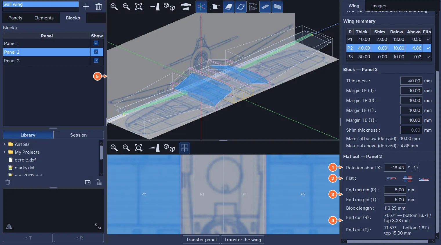
- Rotation about X: the angle, from -45° to 45°; 0 cuts the panel in place, a positive value lowers the outer rib (T). The small button to the right of the field brings the angle back to 0, the cut in place; it is grayed out as long as the panel is not rotated.
- Flat: three buttons, with the alignment icons of the Dihedral (lower surface) frame, compute the rotation that makes the top line, the center line or the bottom line of the panel horizontal, the line that joins the highest points, the mid-heights or the lowest points of its two ribs. The angle stays editable afterward.
- End margin (R) and End margin (T): the material left along the span beyond the farthest point of each end cut, for the guillotine (5 mm by default). The wing tip, the outer rib of the last panel, stays square: no guillotine and no margin, and the face of the block runs through the middle of the rib; on that panel, End margin (T) is grayed out.
- Block length (read-only): the length of the block along the wire, the true length of the panel plus the end margins.
- End cut (R) and End cut (T) (read-only): for the simple guillotine, with the block turned 90° on the table and the chord along the wire, the angle of the guillotine from the table, then the distance between the end face of the block and the cut line on its bottom face and on its top face (for example “83.23° — bottom 4.41 / top 9.16 mm”); a negative distance means the line comes out through the end face. On the wing tip, the row reads “square (wing tip)”.
The rows under the first two are grayed out, label and field, as long as the rotation is 0.
A rotated panel lies alone on the table: it has no shim (its Shim thickness is grayed out at 0), the Vertical position of the lowest point is the material under its own lowest point, and its height is measured on the two faces of its block. Heights 5 and Heights 10 give it its flat height plus twice the value, with no shim. With Repeat P1 block thickness, the common thickness also applies to the flat panels: a wing with several dihedrals, all its panels cut flat, is cut from sheets of a single thickness. In the 3D views, the block of a rotated panel is drawn tilted with it, longer than the panel and without a shim, and each oblique end cut, the plane of the vertical rib through the block, is drawn in a color of its own.
On transfer, the panel is cut between the two faces of its block and the document carries its end cuts (section 8.9): the Guillotine frame of the Cutting tab offers them under End angles, which set the angle and the height of the guillotine and show in the 3D view how to place the block (Cutting › Guillotine).
8.8 Background images
To reproduce a wing from a plan, the Images sub-tab of the right column holds the Background images frame (chapter 12).
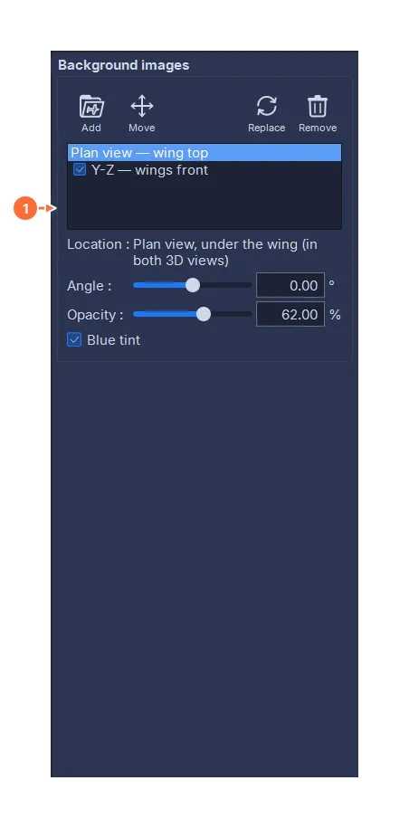
- The Background images frame:
- The first row, Plan view, is the plan of the wing, laid flat at table level (the X-Z plane at Y = 0), under the wing, in both 3D views; it is always there, “no image” as long as no plan is chosen. Add picks an image from the bank (chapter 12; an empty bank first opens its manager) and places it at the center of the wing; Replace puts another image in its place, keeping its settings; Move arms the move: the plan is then dragged with the mouse in the lower view (a rotation gesture leaves this mode); Remove takes it away (after confirmation). The Angle, the Opacity and the Blue tint set the display. The scale of the plan is the one calibrated in the bank: an image calibrated once is to scale everywhere.
- The following rows are the free images, laid on the coordinate planes of the 3D views (chapter 12). A front view of the aircraft, on the Y-Z plane, reads the right way round in the front view.
The plan is fixed in the tab’s coordinate system: the spacing, the span, the sweep and the dihedral slide the wing under the plan, never the plan. The wing places itself in this coordinate system by its own rules: the aircraft’s centerline on the green axis line (X), its rearmost point on the blue line (Z), its lowest point at the vertical position of the blocks page (section 8.7). So you register the plan once with Move, the drawing’s aircraft centerline on the green line and the rearmost point of its trailing edge on the blue line, then you set the wing’s dimensions: the wing matches the drawing when they are right. On a wing whose rearmost point is at the trailing edge of the tip, the first rib slides under the drawing while the sweep is being set, and meets it at the right value. The plan stays at table level; for another height, lay the drawing as a free image on the X-Z plane, whose Offset is the height above the table. In Assembly, the plan view keeps the same place relative to the wing (chapter 11). This principle, images and geometry not linked, applies in every tab (chapter 12).
The plan view button, in the 3D view toolbar, shows or hides the plan in both views; the button next to it does the same for the free images. On transfer, the images that fall on a plane of the document go into that document (section 8.9).
8.9 Transferring a panel
Transfer panel takes the active panel and converts it into a workspace document, a two-path cutting project, named W1.3 for panel 3 of wing 1. Transfer the wing transfers all the panels at once, each into its own document; nothing is written until every panel is ready, and a panel that the transfer refuses stops the whole operation, which names it.
- side 2 (red) receives the inner rib (R), side 1 (blue) the outer rib (T), the spacing is the panel’s span, and the sweep and the dihedral are the panel’s;
- a panel cut flat (section 8.7) is cut between the two faces of its block: each side receives the section of the rotated panel on the face of the block, elements and pre-cut included, the spacing is the block length and the vertical position is that of the blocks page. The document also carries the panel’s end cuts (none at the wing tip, which is left square), for the guillotine of the Cutting tab (End angles, Cutting › Guillotine);
- the two paths are synchronized: each corner of the structure (trailing edge, leading edge, entry and exit of each element) is a synchronization point, and the points are distributed between them as Design’s synchronization tool does;
- the elements are inserted into the path, with the junction paths marked; the pre-cut elements form the first pass, placed at the start of the path;
- the profile’s points and the insertion point of each element are the document’s chord points (Design’s Chords mode, chapter 4): the chord and the block are computed on the profile, without the shapes of the elements;
- a light synchronized cleanup (0.02 mm, chapter 4) is applied automatically: it removes superfluous surface points, never a synchronization point, an element point or a junction point, and it keeps one profile point between two junction points (for example between two neighboring spars on a straight lower surface), so that this stretch is still cut with its offset;
- the document’s block is the panel’s block;
- the wing’s images that fall on a plane of the document become background images there (chapter 4): the plan view and the free images laid flat (X-Z plane) become Top view images, a front image (Y-Z plane) a Front view image, a vertical image placed exactly at the station of one of the panel’s ribs (X-Y plane) a Plane 1 image (outer rib) or a Plane 2 image (inner rib). A panel cut upside down receives only the Top view images; a panel cut flat receives none, since its planes are no longer those of the ribs;
- if the panel had already been transferred, the cutting settings of the previous document (approach, exits, position…) and its material are kept.
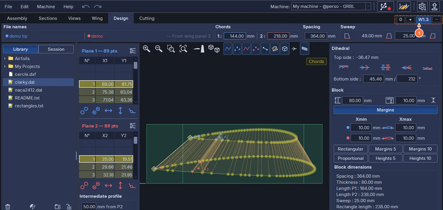
- The chip of the active document, the transferred panel; the Design banner recalls its origin (“From wing panel 3”).
After the transfer, Design shows the document of the first transferred panel. When the panel contains a pre-cut, Design switches to Chords mode to show the plunges that are not part of the profile. The document then opens in Cutting like any project (chapter 5).
A change in Wing that alters the cut of one or more panels already transferred is flagged: a single confirmation request names the panels concerned, whose documents will be deleted and will have to be transferred again. The Cutting settings of these panels and their material are kept, except the settings that refer to a point number. Declining cancels the change; the same goes for Undo and Redo in the Wing tab. A change that alters no cut asks nothing: the spacing, an element’s name, the images, the Show boxes of the blocks. Adding a panel with Add or deleting one with Delete asks nothing either, and does not renumber the documents already transferred. On the document chips, a right-click offers Go to wing panel and Re-transfer from Wing.
8.10 A panel wider than the table
When the panel’s span (the length of its block for a panel cut flat) exceeds the table width of the active machine, the transfer opens a window to split the panel into pieces; it also opens when the panel already has stored cuts. Transfer the wing opens it for each panel concerned, and Cancel abandons the whole transfer.
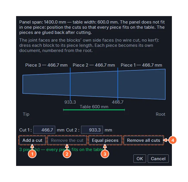
The strip shows the panel, the outer rib on the left (“Tip”), the inner rib on the right (“Root”), with the cut lines and the width of each piece; a piece that is too wide is in red, and OK stays grayed out as long as a piece does not fit. The lines are moved with the mouse; one field per cut gives the exact position.
- Add a cut in the middle of the widest piece.
- Remove the cut that is selected.
- Equal pieces spreads the cuts evenly.
- Remove all cuts: the panel is transferred as a single document (for a table wider than the stored cuts).
Each piece becomes a document, W1.3.1, W1.3.2…, numbered from the inner rib. The joint faces are the faces of the blocks, with no pass of the wire: each block must be dressed to the length of its piece, and all the pieces share the same block thickness and the same bottom, so that, placed end to end, they rebuild the panel’s cut. The Top view and Front view images go to every piece, the Plane 2 image to the piece at the inner rib, the Plane 1 image to the one at the outer rib. For a panel cut flat, the cut positions are counted from the face of the block on the inner-rib side; the first piece keeps the R end cut, the last one the T cut, and a middle piece has none. The cuts are stored with the panel; the wing is designed independently of the machine.