3.1 The areas of the window
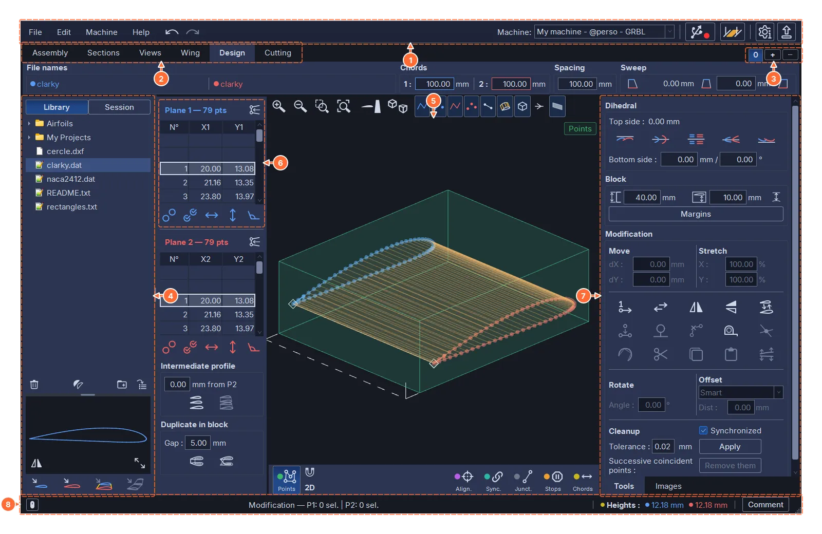
- The toolbar: the menus, Undo and Redo, the active machine and its status dot, the machine configuration, the settings, the return to the startup screen.
- The six tabs.
- The documents of the workspace.
- The file library, with its viewer.
- The 3D view.
- The point lists of side 1 and side 2.
- The tab’s parameters and tools, on two pages, Tools and Images, chosen with the tabs at the bottom of the column.
- The status bar.
The columns are resized by dragging the handles between them. In the Assembly, Sections, Views and Wing tabs, the left column collapses completely when its handle is dragged to the edge of the window; dragging the handle the other way opens it again. A collapsed column does not stay collapsed at the next launch: it gets its last width back.
Only one HotWire4X runs at a time. Launching the software while it is already open brings the open window to the front (a minimized window is restored). A .hw4x file opened by a double-click at that moment is not loaded: open it from the window, with File ▸ Open project….
3.2 The toolbar
3.2.1 The menus
- File: New ▸ New project or New document; Open project…; Recent files; Import documents… (the documents of another file are added); Save (Ctrl+S) and Save As…; Import profile ▸ to Plane 1 or Plane 2; Vectorization… (chapter 13); Reference images… (chapter 12); Export (see below); Preferences… (the settings, see further down); Return to splash; Quit.
- Edit: Undo and Redo.
- Machine: Find interface; Machine configuration…; Manual movement…; Flash the Mega 2560… and Flash the IPL5X… (chapter 6).
- Help: About HotWire4X (the version, the links to the terms of use, the compatible hardware and the third-party licenses); Open examples folder; Online guide; License… (chapter 16).
The entries of File ▸ Export depend on the tab shown. On the Design tab: Export Plane 1…, Export Plane 2… and Export intermediate profile… (chapter 4). On the Views tab: Export Side View outline… and Export Top View outline… (chapter 10). An entry is active only on its tab and when there is something to export. These exports require an active license (chapter 16).
3.2.2 The buttons
On the left, after the menus, Undo and Redo (Ctrl+Z, Ctrl+Y) act on the tab shown (see below). The right part of the bar holds the machine and the settings.
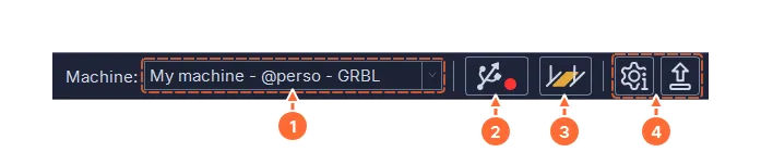
- Machine: the active machine. Choosing another one of the same family activates it at once; choosing a machine of the other family (GRBL versus IPL5X) offers to return to the startup screen.
- Find interface and its status dot: green when the interface is recognized and compliant, amber when its settings differ, red with no interface (chapter 6). The tooltip gives the details.
- Machine configuration opens the window of chapter 6.
- Settings and information opens the settings; Return to splash closes the session and goes back to the startup screen, to change interface. An unsaved project is offered for saving.
3.3 The six tabs
From left to right, in the order of a complete project:
- Assembly: the 3D model of the elements (chapter 11).
- Sections: volumes built from sections (chapter 9).
- Views: volumes built from two silhouettes (chapter 10).
- Wing: wings (chapter 8).
- Design: the paths of any part (chapter 4).
- Cutting: the cut of the active document (chapter 5).
The first four are modules that can be hidden in the settings when they are not used; Design and Cutting are always there. A file that contains elements of a hidden module still opens: a message says so, the elements are loaded and the tab stays hidden. The software opens on Design. When a file is opened, it goes to the most useful tab: Assembly if the file contains elements, otherwise Design, on the first document that contains geometry.
3.4 The workspace and the documents
A .hw4x file is a workspace: it contains documents (the two-path cutting projects, the ones Design and Cutting work on), the elements of the Wing, Sections and Views tabs, the assembly and the reference images.

The documents are shown as chips at the top right of the tabs. On the Design and Cutting tabs, which show the active document, the chips are drawn as tabs open onto the page; on the other tabs, they are buttons. The pressed chip is the active document, the one Design and Cutting show:
- 0 is the working document, always present;
- 1, 2… are free documents, created with +, with File ▸ New ▸ New document, by duplicating a document, by splitting a project at the intermediate profile (chapter 4) or by importing documents;
- W1.1, W1.2… are the panels transferred from a wing (W1 = wing 1, .1 = the first panel; a panel cut into pieces adds a third number);
- S1.1, S1.2… are the sheets transferred from a sections element;
- V1.1, V1.2 and V1.C are the two passes of a views element and the two chained together.
Clicking a chip activates the document. From Assembly, Sections, Views or Wing, the software also switches to Design; from Cutting, it stays on Cutting, which shows the chosen document.
Documents are managed from the Design tab: the ⋯ button (for the active document) and a right-click on a chip offer:
- New document (from the ⋯ button only);
- Rename…: the name given appears in the chip’s tooltip;
- Duplicate;
- Empty, for a free document that contains points: all its points are removed, after confirmation; the document keeps its block settings, its cutting settings and its comment, and Undo brings the points back;
- Delete, after confirmation: document 0 cannot be deleted; deleting a panel transferred from a wing removes all the documents of that panel, pieces included;
- for a wing panel, Go to wing panel and Re-transfer from Wing.
A chip’s tooltip gives the name of the document, or the origin of a wing panel (“Wing panel 2”, “Wing panel 2 — piece 1/2”); the Design banner also recalls this origin.
The window title shows the file name; an asterisk flags unsaved changes, whatever the tab in which they were made.
3.5 The file library
The left column of the Design, Wing, Sections and Views tabs shows the same library. At the top, two buttons choose the source: Library shows the tree of the Library folder; Session shows the profiles of the open project, sorted by tab and then by element, which lets you reuse in one tab a profile drawn in another without going through an export. Below, a viewer draws the selected file or profile; at the bottom, each tab has its own import buttons. The library is described in detail in chapter 4; the supported file formats are in chapter 14.
3.6 Undo and Redo
Undo and Redo in the toolbar, Ctrl+Z and Ctrl+Y, or the Edit menu act on the tab shown: each editing tab (Design, Wing, Sections, Views, Assembly) keeps its own history, up to 40 states. In Design, each document has its own history. The Cutting tab has no history: an undo in Design changes neither the material nor the document’s cutting settings.
3.7 The settings
Settings and information, or File ▸ Preferences…, opens the software’s settings, in pages:
- About: the version, the license and its status, Manage license…, the links to the terms of use, the compatible hardware and the third-party licenses (chapter 16), the Qt library notice.
- Language: the language of the interface, applied by restarting the interface (back to the startup screen, offered when the change is confirmed).
- Data folder: the location of the
HotWire4Xfolder (chapter 2). Browse… moves the data into the new folder, or reuses the data there if the folder already contains some; Use default folder goes back to Documents. The license stays on the computer. - DXF / SVG import: the curve discretization (the number of segments for a full circle; arcs and splines in proportion) and the auto-cleanup tolerance applied right after the import (0 disables it). Default restores each value.
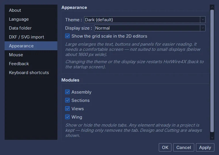
- Appearance: the dark (default) or light theme, the display size, Normal or Large (larger text, buttons and panels; not recommended below 1600 pixels wide), the grid scale of the 2D editors, and the modules: show or hide the Assembly, Sections, Views and Wing tabs (hiding a tab removes nothing from the project). The theme and the size require restarting the interface.
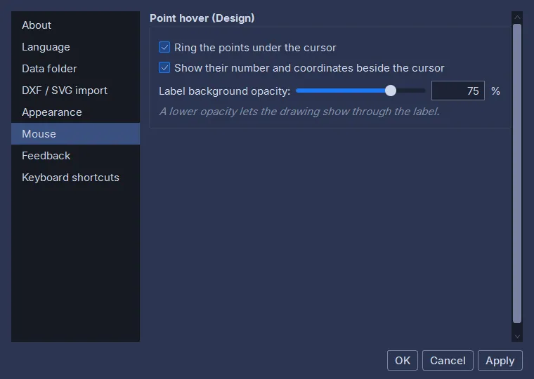
- Mouse: the point hover of the Design tab (chapter 4): ring the points under the cursor, show their number and coordinates beside the cursor (two boxes, checked at first), and the background opacity of this label (75 % at first; the field next to the slider gives it exactly). The setting applies with Apply or OK, without a restart.
- Feedback: a sound at the end of a cut or at a stop point; the display of the welcome card on an empty project.
- Keyboard shortcuts: the shortcut of the communication log (a debugging window showing the exchanges with the interface).
Apply and OK save; Cancel closes without changing anything.
3.8 The status bar
Its content depends on the tab:
- Design: on the left, the mouse button: its tooltip recalls the gestures of the active mode, and a click opens the Keyboard and mouse window, which sits on the right half of the main window and stays open while you work. It first gives the gestures shared by Points mode and the 2D editors (the keyboard, Esc first, then selecting and moving), then what is specific to Design (the marking modes, the magnifier, the two sides, the view, the tools and the lists) and to the 2D editors, in “To… / Do” tables. The same button appears in the Sections and Views tabs; in the center, the selection mode (followed by “(2D)” with the 2D button) and the number of selected points on each side (for example “Modification — P1: 0 sel. | P2: 0 sel.”), with, in Points mode, the X and Y extent of the selection as soon as a side has two selected points or more, followed where needed by the number of null segments, a disabled side (“P2 disabled”) or the points that a drag leaves behind (chapter 4); on the right, the heights (the thickness of each side, in millimeters, measured on the points of the profile) and the Comment button, which opens the project comment.
- Cutting: on the left, Show G-code and the ⛶ button, which enlarges the G-code (GRBL interface only), then the red License off indicator as long as no license is active (chapter 16); in the center, the current point of the simulation and the speeds of the four axes, followed where relevant by the face speed ratio and the number of overshoots, then the progress during a cut (chapter 5); on the right, the Comment button.
- Sections, Views: on the left, the mouse button, which opens the same Keyboard and mouse window (the gestures of the 2D editors are shown only there); then the dimensions of the section or of the element (chapters 9 and 10), followed, when points are selected, by their number (“3 point(s) selected”).
- Wing: the active panel (“Panel 2 / 3”) and the gesture that selects another one.
C:\Github\hotwire4x-site\src\assets\captures\manual\fenetre-survol-pastille.pngHover over the status dot of the toolbar to make its tooltip appear; frame the top right corner of the window.