A three-view drawing, a photo, a sketch: HotWire4X shows them behind the drawings so that you can trace them: in the 2D editors of the Sections and Views tabs, under the wing in the 3D views of the Wing tab, on the planes of a document of the Design tab, and on the coordinate planes of the 3D views. All these images come from a single bank, saved in the project file: an image imported and calibrated once (so many millimeters per pixel) is at the right scale wherever it is placed.
The screenshots show the Corsair bank (Corsair F4U.hw4x): a three-view drawing, the source of fourteen crops (the views) placed in the various tabs.
12.1 The Reference images window
File ▸ Reference images… opens the bank manager; it also opens from the Add button of a Background images frame when the bank is empty, or from the + of the image picker.
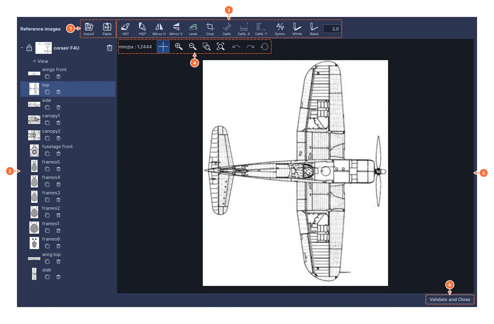
- Import… loads an image file (PNG, JPEG, BMP, GIF, TIFF, WebP) or a PDF, DXF or SVG drawing (see below); Paste takes the image from the clipboard. An image of less than 2400 pixels on its long side is imported whole: a name is asked for, prefilled with the file name, then the image is converted to grayscale and reduced if it exceeds 1600 pixels (the project file stays light). A larger image is imported by zones (see below). An unreadable file is flagged by the message “Cannot open the file”. An image already in the bank is not added a second time: it is simply selected.
- The image tree, on two levels: the source (the imported image, with its padlock and its trash can) and, below it, its views (editable copies derived from the source: a cropped detail, a straightened view, a completed half). The View row, marked with a +, just under the source, creates a new view; each view has its Duplicate and trash can buttons. A double-click renames; a right-click offers New view, locking a source, Duplicate, Rename… and Delete. An uncalibrated image has a warning triangle under its name; an image whose scale is linked to others has a chain link followed by a number (see below).
- The preparation tools, applied to the selected image (section 12.2).
- The bar of the drawing area: the scale of the image in mm/px (preceded by a warning triangle as long as the image is not calibrated), the crosshair (on by default, to crop and calibrate precisely), the zoom (in, out, selection, all), Undo, Redo and the reset to the starting image, which discards the changes made to this image since the window was opened.
- The image; the mouse wheel zooms, the right button pans.
- Validate and Close. Esc does not close the window: it only releases the armed tool (calibration, cropping…) and the clicks already made.
Changes are applied immediately to the image shown, with an undo history for each image (Ctrl+Z, Ctrl+Y), and saved when you move to another image or close the window.
12.1.1 Sources and views: the lock
A source is normally locked: it is read-only and the preparation tools are grayed out; views are derived from it, it is not cut into. Opening its padlock lets you edit it in place; closing it again validates the change. Each time the window opens, all the sources are locked.
An image that has just been imported or pasted, on the other hand, arrives unlocked, and the New image window recalls the steps to follow (for an image imported whole, it first recalls that the image, under 2400 px on its long side, is imported whole, reduced to 1600 pixels if it is larger):
- set its scale with Calib., Calib. X or Calib. Y (section 12.2);
- lock it (padlock) before creating its views, which will then be to scale automatically.
A view is always derived from a locked source: it copies the image and its scale at the moment it is created; editing the source afterward does not change the views already created (except the scale of the images of the same import by zones, see below). View or New view on a source that is still unlocked offers to lock it first, then creates the view. When the source is not calibrated yet, the question warns that the view will not be to scale, and the default answer is No.
12.1.2 Importing a PDF, DXF or SVG drawing
Plans are often supplied as drawings: a PDF (often the print of a DXF), the DXF itself, or an SVG, sometimes on large sheets. A whole A0 sheet reduced to 1600 pixels gives only about 0.7 mm per pixel, too coarse to trace a profile. Import… therefore accepts these files and opens the Import by zones window, where you choose zones of the drawing: each zone is converted separately, at 1600 pixels on its longest side. The smaller the zone, the finer the detail: on the A0 sheet of the screenshot, the side view (550 mm long) gives 0.34 mm per pixel, the fin 0.17 mm.
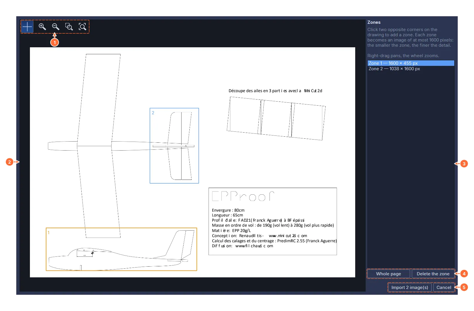
- The crosshair and the zoom (in, out, selection, all). For a PDF with several pages, a list placed before these buttons chooses the page.
- The drawing: clicking two opposite corners adds a zone, numbered on the page; the selected zone is in orange. You chain the zones without doing anything else. A right-drag pans, the mouse wheel zooms; Esc abandons a zone of which only one corner has been clicked, and never closes the window (which would lose the zones already chosen).
- The list of zones, with the size of the image each one will give; selecting a zone of another page shows that page.
- Whole page adds the page shown as a single zone; Delete the zone (or the Delete key) removes the selected zone.
- Import 2 image(s) adds one image per zone to the bank; Cancel adds nothing.
Depending on the format:
- PDF: each page of the file; a list chooses the page.
- DXF: the model space only (layouts are not taken), on a single page. Lines are drawn in black, one pixel thick whatever the zone: a thin CAD line stays sharp.
- SVG: the whole drawing, on a single page. Graphic effects (filters, masks) are not rendered; plans exported from a CAD program or from Inkscape come through well.
Each zone becomes a source, named after the file and the zone (“Plan_ensemble_EPProof — zone 1”, with the page number when the PDF has several); no name is asked for, a double-click renames. The images arrive unlocked and uncalibrated, like any imported image, whatever the format. The file itself is not kept: only the images stay in the project.
The zones of the same import nevertheless keep their proportions: each one arrives with a provisional scale taken from the drawing (one DXF or SVG unit counted as 1 mm, a PDF at its paper size), so that they are at the same scale relative to one another. They form a group, marked in the tree by a chain link and a number: 1 for the first import by zones of the workspace, 2 for the next one, and so on. Within a group:
- calibrating one zone (section 12.2) calibrates all the others, and their views, including those created before; the warning triangle disappears from all of them. The calibration passes to the other images when you leave the calibrated image or lock it: until then, Undo removes it without touching the others;
- a click on the padlock of a zone locks or unlocks all the zones of the group.
To give another scale to part of the plan (a detail drawn at another scale on the same sheet), import the same file again: its zones form a new group, independent of the first.
12.1.3 Importing a large image
An image of 2400 pixels or more on its long side, imported or pasted (a scanned plan, a large photo), also opens the Import by zones window: reduced in one go to 1600 pixels, it would lose the details to trace. Each zone becomes a source of at most 1600 pixels, never enlarged: a zone of 1600 pixels or less keeps all the pixels of the image, a larger zone is reduced to 1600 pixels. The smaller the zone, the finer the detail, up to the resolution of the image: on a plan scanned at 300 dpi, a zone of at most 135 mm on its long side keeps all the pixels of the scan.
The window is the same as for a drawing, on a single page; Whole image replaces Whole page there. The zones are named after the file (“Pasted image — zone 1” for a pasted image) and arrive, like those of a drawing, unlocked, uncalibrated and linked into a group: calibrating one calibrates all the others. Their provisional scale counts one pixel of the original image as 1 mm; the dpi resolution written in the file, often wrong, is ignored.
A very large image opens too, even an A0 sheet scanned at 300 dpi; a file that cannot be read as an image (damaged, empty or too large) is flagged by the message “Cannot open the file”.
12.2 Preparing an image
The tools, from left to right:
- -90° and +90° rotate the image by a quarter turn; Mirror H and Mirror V flip it.
- Level straightens the image: click two points of a line of the plan that should be horizontal (the fuselage axis, a dimension line), and the image rotates by the required angle.
- Crop: click two opposite corners, and the image is cut to the rectangle.
- Calib., Calib. X, Calib. Y calibrate the scale: click two points a known distance apart (two dimension marks, the two ends of a span), then enter the real length in millimeters: the distance between the points, or their horizontal spacing alone, or their vertical spacing alone (a plan is often dimensioned along one axis). The mm/px ratio is that of the whole image; an uncalibrated image has a warning triangle in the tree and in the bar.
- Symm. completes a half-view by symmetry: click two points of the axis (Shift snaps it to 0°, 45° or 90°; hovering over an edge of the image and clicking takes that edge as the axis), then the side to keep; the image is enlarged to hold the reflection.
- White and Black draw strokes, of the thickness shown, in two clicks: a white stroke erases a stray line or opens a passage, a black stroke closes an outline or repairs an image. The stroke stays armed for the next ones.
The calibration tools apply only to an unlocked source: a view inherits the calibration of its source, which guarantees the same scale for all the views of the same plan. Everything else applies to a view or to an unlocked source.
Deleting an image removes it from every place where it is placed (the locations and the free images of the tabs and of the assembly, the background images of the Design documents); the window gives the number of uses before confirming. Deleting a source also deletes its views.
12.3 The Background images frame
Each tab has a single Background images frame, which gathers all its images: in the right page of the Sections and Views tabs, in the Images sub-tab of the Wing tab, under Placement in the Assembly tab, and in the Images page of the right column of Design (chapter 4). Each row reads “location — image name”.
The locations come first: the places the tab provides for tracing.
- Sections: the edited section (“Left section of segment 2”), drawn behind the curve of the 2D editor; the row follows the chosen segment and face.
- Views: Side View and Top View, behind the curve of each view.
- Wing: Plan view, the plan of the wing, laid flat at table level, under the wing, in both 3D views (chapter 8).
A location row is always there, “no image” in italics as long as it is empty. It has no box: whether its image is shown depends on the tab’s buttons (the Image button of the 2D editor banner, the buttons of the 3D views, chapters 8 to 11).
Then come the free images, laid in the 3D views on one of the three coordinate planes, to scale: a side-view plan in the vertical plane, a top view in the horizontal plane, a front view… They are attached to the element (a wing, a sections element or a views element) and, in Assembly, to the assembly itself; each one has its own display box. The Assembly and Design tabs have only free images.
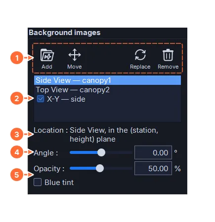
- Add, Move, Replace and Remove.
- The list: the locations, then the free images; select a row to adjust it.
- Location: where the image is (“Side View, in the (station, height) plane”, “Right section of segment 3, station 500.00 mm”…).
- The angle, in degrees, positive counter-clockwise.
- The opacity and the blue tint.
- Add opens the picker below. When the tab has an empty location, the picker asks where to place the image: on one of the empty locations, or as a free image; with no empty location, the image becomes a free image. A location image is placed at the center of the 2D editor, or at the center of the wing.
- Replace puts another image from the bank in place of the selected image, keeping its place and its settings. This is how you change the image of a location that is already occupied.
- Move arms the move of a location image: you drag it with the mouse in the 2D editor (in the Views tab, the view concerned becomes the active view), or in the lower view for the wing; the mouse wheel keeps zooming the view; click again to disarm.
- Remove takes the image away (it stays in the bank); for a location, after confirmation, since its placement is lost.
The scale cannot be adjusted: it is the one calibrated in the bank.
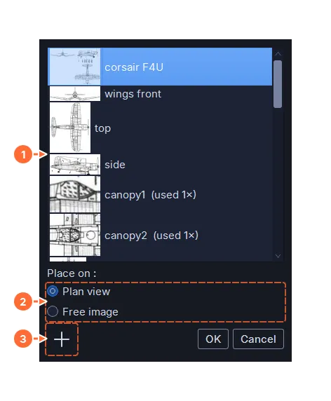
- The images of the bank, with their thumbnail and, for those that are placed, their number of uses (“used 1×”); a click chooses.
- Place on: the empty location, or a free image; the question appears only when the tab has an empty location.
- + opens the bank to import or prepare an image, then returns to the picker with the new image preselected.
12.3.1 The free images
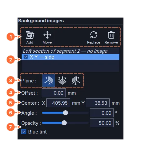
- Add, Move, Replace, Remove.
- The list; the box of a free image shows or hides it.
- The plane: X-Y, X-Z or Y-Z.
- The offset along the normal to the plane (to move a side-view plan back behind the part).
- The center of the image in the plane.
- The angle in the plane, positive counter-clockwise.
- The opacity and the blue tint.
Move locks the 3D view facing the plane of the image: from the side for X-Y, from above for X-Z, from the front for Y-Z. In this view, the image reads the right way round, never mirrored. You then drag it with the mouse as in 2D, and the mouse wheel zooms; rotating the view (middle button, Alt + left button) disarms the move. In Assembly, the free images of the elements follow their element, and the images that belong to the assembly itself are adjusted in place.
In the Design tab, the free images belong to the document and are laid on its planes, Plane 1, Plane 2, Top view and Front view (chapter 4).
12.3.2 Images and geometry
An image is not linked to the part it helps to draw: it stays fixed in its tab’s coordinate system, whatever dimension is changed, and the part places itself in this coordinate system by its own rules (for the wing: the aircraft’s centerline, the rearmost point and the vertical position, chapter 8). To make a part match its plan, place the image once, then set the dimensions: the part meets the drawing when they are right. Only free images can be placed anywhere in space; a location image (the wing’s plan view, the image of a section or of a view) moves within its plane.
An image follows the geometry in a few cases only:
- Design: the placement of the block, which Design redoes by itself after a change, moves the whole panel and carries all the images with it; the Plane 1 and Plane 2 images belong to their plane (the Plane 2 image follows the spacing, and Swap Plane 1 / Plane 2 swaps them). The sweep and the dihedral slide Plane 1 over the drawings, Plane 2 staying on its own (chapter 4).
- Sections: the image of a section stays at the station of its section.
- Assembly: the images of an element follow it when it is placed, so that the fit made in its tab stays right (chapter 11).
- Transfers to Design: the images are copied once, when the document is created, with no link afterward (next section).
12.4 The images in transferred documents
A transfer to Design carries some images over into the documents it creates: those that fall exactly on a plane of the document, seen the right way round. There they become background images (chapter 4), which are adjusted and removed like the others; a new transfer replaces the documents, images included.
- Wing (chapter 8): the plan view and the free images of the X-Z plane go to Top view; an image of the Y-Z plane (a front view, for the dihedral) goes to Front view; an image of the X-Y plane placed at the station of a rib of the panel goes to the plane of that rib, Plane 1 or Plane 2. An image placed between two ribs or on the mirrored half-wing is not carried over. A panel turned upside down for a pre-cut from the top receives only its Top view images; a panel cut flat, rotated in its block, receives none. A panel cut into pieces gives the image of each plane to the piece that carries that plane, and the Top view and Front view images to all the pieces.
- Views (chapter 10): the image of the side view and that of the top view each go to Plane 1 of their document; the combined document receives both, each one under its pass. The free images of the element are not carried over.
- Sections (chapter 9): no image is carried over, since a sheet carries several segments side by side.
12.5 What is saved
The bank is part of the .hw4x file: each image is saved in it once, in compressed grayscale (as PNG or JPEG, whichever is lighter: a line drawing is saved without loss), with its name, its scale and its views; the locations, the free images and the background images of the documents store only their placement. Importing the same image twice does not create a duplicate.